
Related Manuals for Vision & Control pictor M1821


Summary of Contents for Vision & Control pictor M1821
- Page 1 Instructions for Use pictor M1821 Intelligent Camera 999.994.259.10-en-1.4 © Vision & Control GmbH 2014...
- Page 2 M1821 Impress Publisher / Manufacturer Vision & Control GmbH Mittelbergstraße 16 98527 Suhl, Germany Telephone: +49 (0) 3681 / 79 74-0 Telefax: +49 (0) 3681 / 79 74-33 www.vision-control.com Name of the document 999.994.259.10-en-1.4 Date of first issue 16.05.2014 Date modified 06.10.2014...
- Page 3 M1821 Validity This manual is valid for the following devices: Device Order no. Decription pictor M1821/E 4-20-331 1/1,8"CCD, 1600x1200, 20fps, mono, IR cut filter, SVGA-Out pictor M1821/E 4-20-332 1/1,8"CCD, 1600x1200, 20fps, mono, broadband filter, SVGA-Out 999.994.259.10-en-1.4 © Vision & Control GmbH 2014...
-
Page 4: Table Of Contents
M1821 Table of Contents 1. Important Information.................. 6 1.1. Information about the instructions of use............ 6 1.2. Conventions of presentation................7 1.3. Presentation of Safety Instructions............. 9 1.4. Proper and intended use................10 1.5. Improper Use.....................11 1.6. Qualified Personnel................... 12 1.7. Warranty and liability................. 12 2. - Page 5 M1821 7.3.5. Connecting the trigger cable............40 7.3.6. Connecting the video cable............41 7.3.7. Connecting vicolux lighting............42 7.3.8. Connecting the Power supply............44 8. Operation..................... 45 8.1. Switching On and Off (Ready for Operation)..........45 8.2. Operation from the Software Interface............45 8.2.1.
-
Page 6: Important Information
M1821 Important Information 1 IMPORTANT INFORMATION 1.1 Information about the instructions of use This document contains technical information, important instructions for correct installation, commissioning and use, as well as product information which were up-to-date at the time of going to press. -
Page 7: Conventions Of Presentation
M1821 Important Information 1.2 Conventions of presentation The formatting and the symbols in this document help you to use the instructions of use and the device quickly and safely. Product name The instructions of use are valid for the products listed at the beginning. If not referred to expressly by the specific product name, the products described are referred to as "devices". - Page 8 M1821 Important Information Links Links lead to documents outside the instructions for use. Expressly, no guarantee or liability is accepted for the accuracy and security of these documents (such as Internetpages). Links are only active in online-help and the PDF version and with a connection to the Internet. Example: www.vision- control.com...
-
Page 9: Presentation Of Safety Instructions
M1821 Important Information 1.3 Presentation of Safety Instructions Each safety instruction is introduced by a key word and colour highlighted. The key word indicates the degree of danger. The danger and its cause are described, and then the measures to prevent conceivable consequences of the danger. -
Page 10: Proper And Intended Use
M1821 Important Information 1.4 Proper and intended use The devices are designed as an industry-standard image processing system for quality assurance and process automation. The devices may only be used if they are in technically faultless condition and only for their intended purpose, and only in accordance with the specifications in this instructions of use by authorised operative personnel, who are aware of the safety rules and hazards. -
Page 11: Improper Use
M1821 Important Information 1.5 Improper Use All unintended use and all device-related activities not described in this operating manual is to be deemed as unauthorised misuse outside the legal limits of indemnity of the manufacturer Improper usage Reasonably foreseeable misuse is: •... -
Page 12: Qualified Personnel
M1821 Important Information 1.6 Qualified Personnel The device may only be assembled, commissioned, operated, maintained, installed, set up, cleaned, repaired and transported by qualified skilled personnel. Qualified personnel A qualified person is deemed to be someone who has been trained and instructed for his/her activities with the device, and who has proven his/her capability to the purchaser. -
Page 13: Safety Instructions
M1821 Safety Instructions 2 SAFETY INSTRUCTIONS Read the following applicable safety instructions carefully and completely. Follow the instructions for your own safety, the safety of other people, and to avoid damage to the device and the connected technical equipment. Hazards going beyond the general safety instructions are referred to separately at the relevant points in this manual. -
Page 14: Environmental Protection
M1821 Safety Instructions Electrostatic discharge DAMAGE OF PROPERTY Damage to semiconductor components and modules caused by electrostatic discharge. • Do not open the device! Sensitive electronic components and modules can be destroyed by unauthorised interference. Opening the device leads to loss of warranty. -
Page 15: Scope Of Delivery And Accessories
Device pictor M1821 Product DVD with: • Operating software vcwin pro • Instructions for use pictor M1821 as PDF • Instructions for use vcwin pro as PDF • Accesories technical data sheets as PDF Instructions for use pictor M1821 as A5 book Table 1: Scope of delivery 999.994.259.10-en-1.4... -
Page 16: Accessories
M1821 Scope of Delivery and Accessories 3.2 Accessories Description Lenght Order no. PLC/power cable, 12-pin HIROSE socket / 4-40-223 open cable end PLC/power cable, 12-pin HIROSE socket / 10 m 4-40-224 open cable end PLC/power cable, 12-pin HIROSE socket /... - Page 17 M1821 Scope of Delivery and Accessories Description Lenght Order no. SVGA cable for monitor, 10-pin HIROSE 4-40-240 plug / 15-pin Sub-D socket SVGA cable for monitor, 10-pin HIROSE 10 m 4-40-241 plug / 15-pin Sub-D socket SVGA cable for monitor, 10-pin HIROSE...
- Page 18 M1821 Scope of Delivery and Accessories Description Quantity Order no. Key-Pad, incl. V24 serial cable C4 (RS232), 4-40-207 5 m, for the monitor menu Key-Pad, without cable 4-40-204 Key-Pad, V24 serial cable C4 (RS232), 5 m 4-40-208 Table 7: Accessories Key-Pad...
-
Page 19: Product Description
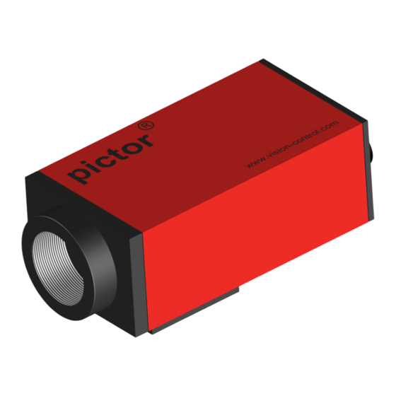
M1821 Product Description 4 PRODUCT DESCRIPTION 4.1 Devices Views Front view C-Mount lens connection Holder for filter Imager Mounting block Image 1: Front view Rear view Ethernet interface PLC/Power interface Video Trig. Trigger-/RS232 interface Monitor interface Mounting block Image 2: Rear view 999.994.259.10-en-1.4... -
Page 20: Image 3: Bottom View
M1821 Product Description Bottom view 2 x M6 thread Vision & Control 98527 Suhl, Germany Type: pictor M1606E No.: E6380152 Label 1 x 1-32 UN2A thread Image 3: Bottom view © Vision & Control GmbH 2014 999.994.259.10-en-1.4... -
Page 21: Product Data
M1821 Product Data 5 PRODUCT DATA Technical Data Image Sensor Device pictor M1821 pictor M1821 Order number 4-20-331 4-20-332 Sensor 1/1,8" CCD global shutter, progressive scan Sony ICX274AL Type mono Filter IR cut filter broadband filter Number of pixels... - Page 22 M1821 Product Data Interfaces Device pictor M1821 pictor M1821 Order number 4-20-331 4-20-332 Communication 1 x RS232, 1 x Ethernet, 1 x TTL Trigger Digital I/Os 4 x Digital IN, 4 x Digital OUT Video out SXGA Monitor 800 x 600...
-
Page 23: Interfaces
M1821 Product Data 5.1 Interfaces Overview of Interfaces LAN / Ethernet interface PLC and power interface Video Trig. Trigger, RS232 or Key-Pad interface Video-Out (SVGA/SXVGA) Image 4: Overview of interfaces 5.1.1 Digital I/O-Interfaces The digital I/O interfaces are only available if the device is connected via the Power/ PLC cable. -
Page 24: Ethernet Interface
M1821 Product Data Parameter Digital Outputs Parameter Number of outputs Power supply* 9.8 V 24 V 28 V Switched potential power supply Output current per output 500 mA Output current all outputs Switching power 24 V DC, 500 mA... -
Page 25: Rs232 Interface
M1821 Product Data 5.1.3 RS232 interface The device has a RS232 interface for serial communication with a process control system (PLC, computer). The baud rate is set in the factory to 9.600 kbit/s. It can be adjusted from the software user interface. -
Page 26: Trigger Interface
M1821 Product Data 5.1.4 Trigger interface The device has a special trigger interface, a dedicated fast TTL trigger input (for use as image capture trigger) and a fast TTL trigger output (Strobe Trigger). Both signals are very fast and have a very low signal to noise ratio, it is recommended to keep the cable as short as possible. -
Page 27: Image 5: Trigger Input Npn
M1821 Product Data ADVICE Input and output are not protected against over current. The output is neither protected against short circuit nor reverse voltage spikes from inductive loads. Block diagram of trigger input Image 5: Trigger input NPN Image 6: Trigger input PNP 999.994.259.10-en-1.4... -
Page 28: Conditions For Operation, Storage And Transport
M1821 Product Data Block diagram of trigger output Image 7: Trigger output 5.2 Conditions for Operation, Storage and Transport The following ambient conditions for operation, storage and transport must be maintained: Conditions that must be maintained Ambient conditions Operation... -
Page 29: Operation Software Vcwin Pro
M1821 Operation software vcwin pro 6 OPERATION SOFTWARE VCWIN PRO If the device is connected Ethernet interface, it can be immediately controlled, parameterised and configured with the vcwin pro operation software. The devices are parameterised with the vcwin pro operation software via the Ethernet interface (recommended) or the RS232 interface. -
Page 30: Installing, Starting And Updating Operating Software Vcwin Pro
M1821 Operation software vcwin pro 6.2 Installing, Starting and Updating operating software vcwin pro ADVICE Administrator rights are required to install the operating software. Installing vcwin pro 1. Insert the supplied DVD into the drive of the host computer 2. -
Page 31: Commissioning
M1821 Commissioning 7 COMMISSIONING 7.1 Unpacking DAMAGE OF PROPERTY Damage or destruction of the device caused by condensation and large temperature differences! • Do not subject the device to large temperature fluctuations. • After storage and transport, allow the device to adjust slowly to the ambient temperature at the place of use. -
Page 32: Mounting
M1821 Commissioning 7.2 Mounting DAMAGE OF PROPERTY Cable damaged by a bending radius that is too small and the lack of a strain relief clamp. • Comply with the specified minimum bending radius. • Cables must generally be mounted with a strain relief clamp. -
Page 33: Image 8: Mounting Holes For Mounting The Device
M1821 Commissioning Mounting holes 1-32 UN 2A 25.0 17.5 30.0 42.5 17.5 28.5 55.5 Image 8: Mounting holes for mounting the device Mounting the Lens 1. Remove the protective film / cap. 2. Screw on the selected lens. Working distance and recording range The working distance, recording range and size of the image field are flexible and dependent on the selected lens. -
Page 34: Connecting
M1821 Commissioning 7.3 Connecting The operating voltage is supplied via the PLC/Power cable or the power plug. Communication takes place via the PLC/Power cable and/or Ethernet, RS232. 7.3.1 Operating Voltage Supply The operating voltage is supplied through the PLC/Power Cable (accessories) or the power supply (accessories). -
Page 35: Connecting The Plc/Power Cable
M1821 Commissioning Connection of the operating voltage supply IN GND CAM PWR Image 9: Connection of the operating voltage supply 7.3.2 Connecting the PLC/Power cable Perform the following steps only in de-energiesed state. 1. Plug the 12-pin Hirose plug of the PLC/Power cable into the I/O socket on the device. -
Page 36: Image 10: Plc/Power Cable Connection
M1821 Commissioning Trig. Image 11: View: socket on camera Image 10: PLC/Power cable connection © Vision & Control GmbH 2014 999.994.259.10-en-1.4... - Page 37 M1821 Commissioning Pin assignments PLC/Power cable Colour Assignment Open cable end 24 V PLC* + 24 V dig. input and output red / blue Operating voltage + 24 VDC black Operating voltage GND pink IN 2 Digital input 2...
-
Page 38: Connecting The Ethernet Cable
M1821 Commissioning 7.3.3 Connecting the Ethernet cable Perform the following steps only in de-energiesed state: 1. Insert the 6-pin HIROSE plug of the Ethernet cable into the LAN socket on the device. 2. Connect the RJ45 plug to a free Ethernet interface on the host computer or the network. -
Page 39: Connecting The Rs232 Cable
M1821 Commissioning 7.3.4 Connecting the RS232 cable Perform the following steps only in de-energiesed state: 1. Insert the 6-pin HIROSE plug of the RS232 cable into the Trig. socket on the device. 2. Plug the D-Sub plug into a free serial port (COM) of the process control system or the key pad, and screw tight. -
Page 40: Connecting The Trigger Cable
M1821 Commissioning 7.3.5 Connecting the trigger cable Perform the following steps only in de-energiesed state: 1. Insert the 6-pin HIROSE plug of the trigger cable into the Trig. socket on the device. 2. Connect the open end of the trigger cable to control unit. -
Page 41: Connecting The Video Cable
M1821 Commissioning 7.3.6 Connecting the video cable Perform the following steps only in de-energiesed state: 1. Insert the 10-pin Hirose plug of the video cable into the video socket on the device. 2. Connect the 15-pin D-Sub plug with a monitor. -
Page 42: Connecting Vicolux Lighting
M1821 Commissioning 7.3.7 Connecting vicolux lighting Connecting a vicolux lighting with TTL trigger via HIGH/LOW status transition ® Camera vicolux ® +5 V +Trg. -Trg. Trig. Out Image 16: Connection option HIGH/LOW edge Connecting a vicolux lighting with TTL trigger via LOW/HIGH status transition ®... -
Page 43: Image 18: Connection Option With Plc And High/Low Edge
M1821 Commissioning Connecting a vicolux lighting with 24 V PLC control and LOW/HIGH edge at ® the Trigger Out Camera vicolux ® + PLC + 24 V - PLC Trig. Out Image 18: Connection option with PLC and HIGH/LOW edge... -
Page 44: Connecting The Power Supply
M1821 Commissioning 7.3.8 Connecting the Power supply ADVICE When using the power supply (AC adapter), the digital I/O interfaces of the device can not be used. Perform the following steps only in de-energiesed state. 1. Plug the 12-pin HIROSE connector of the power supply into the I/O socket on the device. -
Page 45: Operation
M1821 Operation 8 OPERATION 8.1 Switching On and Off (Ready for Operation) The device is switched on with the operating voltage supplied via the PLC/ Power cable. Disconnecting the device from the operating voltage supply switches the device off. -
Page 46: Interface Settings
M1821 Operation 8.2.2 Interface Settings Use Menu Communication > Interface to configure the interface for communication between the host computer and the device. Settings made here are used in every connection with vcwin pro. Serial connection with the device Image 20: vcwin pro dialogue: Communication Parameters RS232 1. -
Page 47: Image 21: Vcwin Pro Dialogue: Communication Parameters Tcp/Ip
M1821 Operation ICP/IP connection with the device Image 21: vcwin pro dialogue: Communication Parameters TCP/IP 1. Switch to the TCP/IP tab. 2. With the [Search] button, all available devices, on the same subnet, are displayed (UDP broadcast to all participants). -
Page 48: Connect To The Operation Software
M1821 Operation 8.2.3 Connect to the operation software Connect the device with the operation software vcwin pro via: • Menu: Communication > Connect • Toolbar The initialisation of the host computer interface sets up a connection with the device via vcwin pro. The Run Mode is interrupted and the system resources are queried. -
Page 49: Maintenance And Service
M1821 Maintenance and Service 9 MAINTENANCE AND SERVICE 9.1 Maintenance The device is maintenance-free. Depending on the operating environment, it may have to be cleaned. Cleaning the outer face The housing can be cleaned according to the conditions applicable to the given protection class. -
Page 50: Service
M1821 Maintenance and Service 9.2 Service Technical Support Please contact our Technical Support if you have any technical questions concerning our products. Competent employees will deal with your problems and questions. We will be glad to be of service: Monday to Thursday 8:00 to 17:00, and Friday 8:00 to 15:00. -
Page 51: Decommissioning
M1821 Decommissioning 10 DECOMMISSIONING ADVICE The device is decommissioned in the same way as it was commissioned, but in reverse order. The order of the points "Disconnect" and "Dismount" is decided by the accessibility of the device when mounted in the operating environment. -
Page 52: Dismount
M1821 Decommissioning 10.2 Dismount 1. Secure or hold the device firmly. 2. Unscrew the screws holding the device in the holder. 3. If applicable, unscrew the lens. 4. Put the cover on the lens mount. © Vision & Control GmbH 2014... -
Page 53: Disposal
M1821 Disposal 11 DISPOSAL 11.1 Disposal The device and its accessories and packaging must be sent for environmentally compatible recycling. Do not throw electrical devices or tools into the household waste! According to European Directive 2002/96/EC on waste electrical and electronic equipment and its implementation in national law, unusable electric tools must be collected separately, and sent for environmentally compatible recycling. -
Page 54: Appendix
D-98527 Suhl, Germany Representative: Dr. Jürgen Geffe, Managing director We, Vision & Control GmbH Suhl, declare that the products described below • pictor M1821/E have been manufactured in accordance with the following standards and normative documents: • 2004/108/EC – Electromagnetic compatibility •... -
Page 55: Technische Zeichnungen
M1821 Appendix 12.2 Technische Zeichnungen Dimensions Image 22: Dimensions 999.994.259.10-en-1.4 © Vision & Control GmbH 2014... -
Page 56: Spectral Sensitivity
M1821 Appendix 12.3 Spectral sensitivity Image 23: Spectral sensitivity M1821/E © Vision & Control GmbH 2014 999.994.259.10-en-1.4... -
Page 57: Indexes
M1821 Indexes 13 INDEXES 13.1 List of Figures Image 1: Front view..................19 Image 2: Rear view..................19 Image 3: Bottom view.................20 Image 4: Overview of interfaces..............23 Image 5: Trigger input NPN............... 27 Image 6: Trigger input PNP................27 Image 7: Trigger output................ - Page 58 M1821 Indexes Accessories...................... 16 Air humidity ....................28 Ambient conditions..................28 Communication..................22, 34 Connecting....................... 34 Connecting the interface................. 48 Decommissioning..................... 51 Devices Views....................19 Digital I/O-Interfaces..................23 Digital I/Os....................... 22 Digital inputs....................23 Digital Outputs....................24 Dimensions ..................... 22 Dismount......................
- Page 59 M1821 Indexes Housing material....................22 ICP/IP connection.................... 47 Image Sensor....................21 Interfaces....................22, 23 Key pad......................25 Key-Pad......................18 Lens......................... 33 Lens mount...................... 22 Mounting....................22, 32 Number of pixels..................... 21 operating voltage..................34, 45 Operating Voltage Supply................34 photo thread....................
- Page 60 M1821 Indexes Processor......................21 Product name....................7 Protection class....................22 Ready for Operation..................45 rigger cable...................... 40 RS232 cable....................39 RS232 interface....................25 Scope of Delivery.................... 15 Sensor......................21 Serial connection..................... 46 Shutter......................21 storage......................28 SVGA cable for monitor.................. 17 tapped holes....................
- Page 61 M1821 Indexes Weight......................22 Working distance..................... 33 999.994.259.10-en-1.4 © Vision & Control GmbH 2014...
Need help?
Do you have a question about the pictor M1821 and is the answer not in the manual?
Questions and answers