Table of Contents
Advertisement
Quick Links
Advertisement
Table of Contents

Related Manuals for ISYGLT LS-07-PIR-WH Series


Summary of Contents for ISYGLT LS-07-PIR-WH Series
- Page 1 Technical Data / Instruction Manual LS-07-PIR-xx-WH-xx Article no. 8008508x-xx Light and PIR Motion Sensor (passive infrared) Seebacher GmbH www.seebacher.de Phone: +49 (0) 80 41 / 77 77 6 Marktstrasse 57, 83646 Bad Tölz info@seebacher.de Fax: +49 (0) 80 41 / 77 77 2...
-
Page 2: Notes On Documentation
These instructions are intended for qualified personnel who are 1. Notes on documentation familiar with the assembly, installation and operation of the ISYGLT system. It is essential that you read these operating instructions through before commissioning and keep them accessible for further 1.1. -
Page 3: Safety Instructions
Protect module from humidity • and configuration of the ISYGLT module may only be carried out by In addition to these safety instructions, you must also observe trained staff. the special safety instructions listed in the individual chapters for the individual acts. -
Page 4: Warranty
These are limited to the intended use of the module and refer EU on waste electrical and electronic equipment at the local collec- to the repair or replacement of the ISYGLT module. Please send the tion points for waste electrical and electronic equipment! device with an attached error description to our company address given below. -
Page 5: Product Description
The sensor is connected directly to the are individually possible, such as activating the lighting only in the case ISYGLT BUS. The Light Sensor provides a calibratable 16-bit bright- of large movement or maintaining the „ON“ state even in the case of ness value. - Page 6 10.2. Address setting DIP switch 8-pole (is located on the circuit board of the module) • S1 = Reserve (must be set to OFF) • S2 to S8 = Module address ISYGLT 10.3. Function displays Meaning / Function LED red Function can be freely parameterised via the ProgramDesigner.
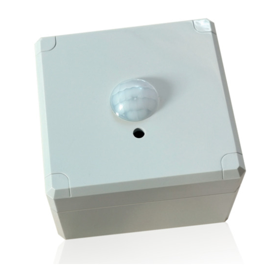
- Page 7 10.4. View LS-07-PIR-01-WH-AP LS-07-PIR-01-WH-APG LS-07-PIR-01-WH-UP LS-07-PIR-02-WH-AP LS-07-PIR-02-WH-APG LS-07-PIR-02-WH-UP Seebacher GmbH www.seebacher.de Phone: +49 (0) 80 41 / 77 77 6 Marktstrasse 57, 83646 Bad Tölz info@seebacher.de Fax: +49 (0) 80 41 / 77 77 2...
- Page 8 11. Detection ranges PIR sensor types LS-07-PIR-01-WH Long Distance Detection Type 108°x99°, 12m Seebacher GmbH www.seebacher.de Phone: +49 (0) 80 41 / 77 77 6 Marktstrasse 57, 83646 Bad Tölz info@seebacher.de Fax: +49 (0) 80 41 / 77 77 2...
- Page 9 LS-07-PIR-02-WH High Density Long Distance Detection Type 69°x69°, max. 14.5m Seebacher GmbH www.seebacher.de Phone: +49 (0) 80 41 / 77 77 6 Marktstrasse 57, 83646 Bad Tölz info@seebacher.de Fax: +49 (0) 80 41 / 77 77 2...
-
Page 10: Wiring Diagram
12. Wiring diagram +24V BUS-A BUS-B BUS address Light / PIR motion sensor LS-07-PIR-xx-xx Art. no.: 8008508x Misprints and technical changes reserved. Seebacher GmbH www.seebacher.de Phone: +49 (0) 80 41 / 77 77 6 Marktstrasse 57, 83646 Bad Tölz info@seebacher.de Fax: +49 (0) 80 41 / 77 77 2...
Need help?
Do you have a question about the LS-07-PIR-WH Series and is the answer not in the manual?
Questions and answers