Advertisement
Quick Links
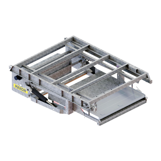
Installation Supplement
M-21-08
REV. B
OCTOBER 2021
RA-45 INSTALLATION SUPPLEMENT
289905-01-200
Domino's Specification,
Main Switch
Center Cable Guide
Junction Box
General Notes:
• Use the standard RA installation manual for structural mounting instructions.
• Use this supplement for electrical installation and wiring.
• Make sure cables are protected from sharp edges with loom and grommets.
• Secure all cables and harnesses to prevent movement.
• Do not attach anything to the liftgate moving harness. Make all connections in Junction
Box.
©2021 MAXON Lift Corp
M-21-08 REV.B
Page 1 of 36
Advertisement

Related Manuals for Maxon RA-45


Summary of Contents for Maxon RA-45
- Page 1 Installation Supplement M-21-08 REV. B OCTOBER 2021 RA-45 INSTALLATION SUPPLEMENT 289905-01-200 Domino’s Specification, Main Switch Center Cable Guide Junction Box General Notes: • Use the standard RA installation manual for structural mounting instructions. • Use this supplement for electrical installation and wiring.
-
Page 2: Jumper Cable
Installation Supplement Installation Supplement Substitution for STEP 3.1 in RA Installation Manual Note: Main Control switch is pre-wired to Junction Box. 1. Connect batteries as shown below to allow running of the liftgate for installation positioning before welding to trailer cross-members. 175 A CIRCUIT BREAKER PRE-INSTALLED IN BAT. - Page 3 Installation Supplement Purkey’s Severe Service Charge Line Connections in Battery Box CONNECTS TO J-BOX CONNECTS TO J-BOX CONNECTS TO PUMP GROUND STUD 12V STUD TERMINAL ASSY SELECTOR SWITCH TERMINAL INSTALL 150 A CIRCUIT BREAKER FROM PURKEY KIT JUMPER CABLE M-21-08 REV.B Page 3 of 36...
-
Page 4: Junction Box
Installation Supplement 3. After fully welding the liftgate, disconnect +12v cables from selector switch to battery and charge line in the battery box to remove power while making Junction Box connections. 4. Run loomed Purkey’s Severe Service Charge Lines from the nose of trailer to center Liftgate Cable Guide. - Page 5 Installation Supplement 7. The backing plate can now be rotated to improve access to cord grips and wires. 8. Run Purkey Severe Service positive and negative charge lines through top two cord grips and install into Junction Box. Crimp 2-gauge battery lugs onto cables and heat shrink. Connect cables as shown below and tighten cord grip outer nuts to compress and seal grommet on cables.
- Page 6 Installation Supplement 9. Run loomed trailer DOME light wires (BLUE & WHITE) in Cable Guide towards Junction Box. Route wires into Junction Box through a single cord grip grommet hole as shown below. Crimp 3/8” ring terminal to the white wire. Heat shrink terminal and connect to 3/8” ground stud.
- Page 7 Installation Supplement 11. Run Purkey’s Direct Trail Charger Harness from the nose of the trailer to Center Liftgate Cable Guide. Route Purkey’s Direct Trail Charger Harness in center Liftgate Cable Guide towards Junction Box. 12. Route into Junction Box through single hole cord grip shown below. Cut approximately 6” off the jacketed portion of the four-wire harness.
- Page 8 Installation Supplement 13. Install wall switches, two outside and two inside, per customer specifications. Route all four loomed Liftgate Wall Switches along cross members, through grommeted cross member holes exiting at the center Liftgate Cable Guide. Secure switch cables to cross members as shown.
- Page 9 Installation Supplement 15. Reconnect +12V cables to Liftgate battery and charge line that were disconnected in step 3. • Check each switch for proper operation. If the switch function does not match the switch decal, swap #1 wire and #2 wire for that switch. POSITION RING TERMINALS FOR WALL SWITCH WIRES AS SHOWN BELOW.
-
Page 10: Battery Box Cover
Installation Supplement 20. Trim 3/8” off lever plate on the right-hand side of lift frame to eliminate interference with mud flap. LEVER PLATE TRIM 3/8” OFF LEVER PLATE AS SHOWN 21. Install QR Code decal in 3 places • Near 7-way nose box, front driver’s side of the trailer. •... -
Page 11: Where Used
Addendum A Addendum A MAX SOL add on Solar Box for Domino’s RA-45 Parts in Solar Box add-on kit Item Description Where Used Solar Box Assembly Step 1. Solar Box to Lift Frame Channel. Bolt, 3/8-16 x 1-1/2” GR8 Step 1. Solar Box to Lift Frame Channel. -
Page 12: Bottom View
Addendum A 1. Attach Solar Box to Liftgate Channel. a. Position Solar Box 14” to the right of the liftgate Junction Box. 14” JUNCTION BOX SOLAR BOX LIFTGATE CHANNEL b. Using the Solar Box as a guide, drill two 3/8” holes into Liftgate Channel. Note: Liftgate can be slid out approximately 24”... - Page 13 Addendum A Remove 2 ½” of jacket portion off on the 4 wires. Cut off unused red and black wire. • REMOVE 2 ½” CUT UNUSED RED OF JACKET. AND BLACK WIRE. Strip 3/8” of insulation off the wire and crimp ¼” female insulated quick connect to the •...
- Page 14 Addendum A 5. Connect Charge Controller data wires to Optio3 WAYPOINT. WHITE wire to BLUE wire and YELLOW wire to YELLOW wire. OPTIO3 WAYPOINT CONNECTIONS 6. Cut ring terminal ends off 3 ft long Charge Controller battery cables. CUT RING TERMINALS OFF END OF CABLE 7.
- Page 15 Addendum A 8. Follow MAX SOL installation instructions (M-20-17) only for mounting solar panel and routing solar panel Home Run cables (PV+ and PV-) into Solar Box. All other MAX SOL connections are covered in this Addendum. The solar panel Home Run cables will be routed in the Liftgate Channel Guide to the Solar Box, as shown below.
- Page 16 Addendum A 10. Route RED and BLACK wires from Optio3 WAYPOINT through cord grip in the Junction Box. Crimp and heat shrink 3/8” ring terminals to wires and connect as shown below. RED AND BLACK WIRE FROM OPTIO3 WAYPOINT RED WIRE WITH 3/8” RING TO 3/8”...
- Page 17 Addendum A 12. Route 3 wire gray cable from Solar Box through cord grip in the Junction Box. • Reinstall backing plate to Junction Box with four screws and spacers removed in step 5. Crimp and heat shrink #10 ring terminals to wires and connect as shown below. •...
- Page 18 Addendum A 16. Route 4 wall switch cables into Solar Box through the lower four-hole cord grip as shown below. • Cut off the excess switch harness. Cut approximately 4” off the jacketed portion of the three-wire harness. Crimp and heat shrink #10 ring terminals to wires and connect as shown below.
- Page 19 Addendum A Verify Optio3 WAYPOINT Operation: 20. Confirm antenna connections are tight and connected as shown. The antenna wires are labeled on the wire near the connector. The 4G/LTE antenna is on the terminal closest to the clear Optio3 cover and the GPS antenna is on the terminal closest to the box bottom. Clear Optio3 cover 4G Antenna GPS Antenna...
- Page 20 Addendum A 23. Use a smartphone or tablet to connect to the Optio3 WAYPOINT Wi-Fi hotspot. Connect to the Optio3 Waypoint Wi-Fi hotspot that matches Optio3 WAYPOINT serial number you are working on. When you are connected, it will show “Connected without Internet.” You are now ready to scan the small QR code labeled “Scan to run local tests.”...
- Page 21 Addendum A 26. After the cellular connection is confirmed, verify the sensors are detecting local connectivity with the GPS and Charge Controller. a. Tap the menu button, then select “Sensors” from the menu to start scanning for connections. b. After approximately 2 minutes, the RS-485 port should highlight green and display “Detected EpSolar charge controller!”...
- Page 22 33. Attach the cover to Solar Box with two ¼”-20 x ¾” bolts, ¼” washers, and ¼” lock washers. 34. Continue with STEP 16 on page 9 of the RA-45 INSTALLATION SUPPLEMENT DOMINO’S SPECIFICATION 289905-01-200. M-21-08 REV.B...
-
Page 23: Troubleshooting
Schematics and Troubleshooting Schematics and Troubleshooting M-21-08 REV.B Page 23 of 36... - Page 24 Domino’s RA-45 Schematics and Troubleshooting 289905-01-200 M-21-08 REV. A System Wiring Schematic – J-Box, Control, Indicators & Lights Page 24 of 36...
- Page 25 Domino’s RA-45 Schematics and Troubleshooting 289905-01-200 M-21-08 REV. A System Wiring Schematic – Pump Assembly & Lights Page 25 of 36...
- Page 26 Domino’s RA-45 Schematics and Troubleshooting 289905-01-200 M-21-08 REV. A System Wiring Schematic – Battery Assembly Page 26 of 36...
- Page 27 Domino’s RA-45 Schematics and Troubleshooting 289905-01-200 M-21-08 REV. A Hydraulics: Schematic Toggle Switch Selects Rotary Switch Selects Gravity Down or Power Pump 1 or 2 Down Operation Page 27 of 36...
- Page 28 Domino’s RA-45 Schematics and Troubleshooting 289905-01-200 M-21-08 REV. A Hydraulics: Valve Locations Pump 1 PUMP BOX 4-Way Valve SV1 Hydraulic Motor Gravity Down Lock Valve SV3 Lock Valve SV4 Hydraulic Lock Valve Hydraulic Lock Valve SV2 on LH Cylinder SV2 on RH Cylinder...
- Page 29 Domino’s RA-45 Schematics and Troubleshooting 289905-01-200 M-21-08 REV. A Hydraulic Hose Fitting Torque & Electrical Values, Power Unit Motor Solenoid Switch Coil Resistance: 5.4Ω @70ºF. ±15% Ampere: (Across #10 coil terminal studs) 2.2A @ 12.5V #10 Coil terminal torque: 10-15 lb.-in max.
- Page 30 Domino’s RA-45 Schematics and Troubleshooting 289905-01-200 M-21-08 REV. A Parts: Main Switch and V-Check 299882-01 SWITCH, MAIN CONTROL QTY: 1296952- 296955-01 V-CHECK GAUGE QTY: 1 Page 30 of 36...
- Page 31 Domino’s RA-45 Schematics and Troubleshooting 289905-01-200 M-21-08 REV. A Parts: Junction Box 906580-04 906580-01 906580-05 906616-04 FUSE, 3 A FUSE, 10 A FUSE, 5 A JNCT BLOCK, 3 STUD QTY: 1 QTY: 1 QTY: 1 QTY: 2 906578-01 907469-01 RELAY, 5 PIN...
- Page 32 Domino’s RA-45 Schematics and Troubleshooting 289905-01-200 M-21-08 REV. A Parts: Pump Box, Cycle Counter & Selector Switches 906578-01 288102-01 210019-01 297269-01 RELAY, 12VDC, 5 PIN PUMP SELECTOR SWITCH CONTROLLER, DUAL PUMP DIGITAL CYCLE COUNTER QTY: 1 QTY: 1 QTY: 1...
- Page 33 Domino’s RA-45 Schematics and Troubleshooting 289905-01-200 M-21-08 REV. A Hydraulics: Pressure Relief Valve Location and Settings Remove cap to access slide “OUT” / “IN” relief valve. Set to 1800 psi. Main Lift relief valve. Set to 2750 psi. Pressure gauge...
-
Page 34: Troubleshooting Chart
Domino’s RA-45 Schematics and Troubleshooting 289905-01-200 M-21-08 REV. A Troubleshooting Chart Problem Possible Cause Correction Platform will not raise, lower, or 1. Power shut off switch in “OFF” Set power shut-off switch to “1+2” position. move in & out, and motor will not position. - Page 35 Domino’s RA-45 Schematics and Troubleshooting 289905-01-200 M-21-08 REV. A Troubleshooting Chart Problem Possible Cause Correction 2. SV3 (in) valve not shifting. Check electrical connections at valve. SV1 & SV3 (out) valves not shifting. Remove and clean valve if needed. 3. Low pump pressure.
- Page 36 Domino’s RA-45 Schematics and Troubleshooting 289905-01-200 M-21-08 REV. A Troubleshooting Chart Problem Possible Cause Correction Platform not going up or down, 3. Cylinder flow control valves blocking Tighten cylinder flow control valve to 5 ft-lb. motor runs. - Continued port.
Need help?
Do you have a question about the RA-45 and is the answer not in the manual?
Questions and answers