Table of Contents
Advertisement
Quick Links
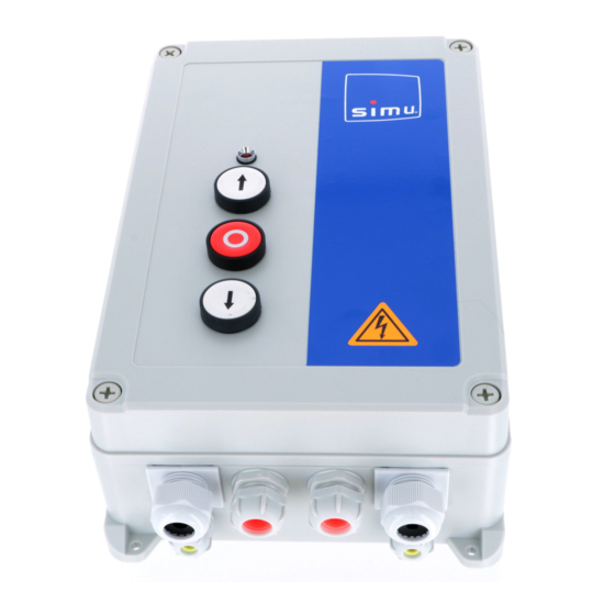
CONTROL BOX
SIMUDRIVE SD510
SIMU S.A.S. au capital de 5 000 000 € - Zone Industrielle Les Giranaux - 70100 ARC-LÈS-GRAY - FRANCE - RCS VESOUL B 425 650 090 - SIRET 425 650 090 00011 - n° T.V.A CEE FR 87 425 650 090
1
SAFETY INSTRUCTIONS
1.1 Caution – Important safety instructions
For reasons of personal safety, it is important to follow all the instructions, as incorrect installation can lead
to serious injury. The control box must be installed and adjusted by a professional motorization and building
automation installer, in compliance with the regulations of the country in which it is going to be used.
The installation and user manual must be given to the end user, explicitly stating that installation, adjustment
and maintenance of the motorization must be performed by a professional motorization and building
automation installer.
1.2 Introduction
This control box is designed to control three-phase SIMU motors (<1250W) roll-up or sectional doors in
commercial or industrial
A LED screen allows to check and detect any operating anomalies in the control unit or on the connected
devices. This product, installed according to these instructions, complies with EN 12453 et EN 12445.
These instructions are especially designed to ensure the safety of property and people.
1.3 Safety instructions relating to installation
WARNING! An incorrect installation or improper use of the product can cause damages to people,
animal or things.
• Scrap packing materials (plastic, cardboard, polystyrene etc.) according to the provisions set out by
current standards. Keep nylon or polystyrene bags out of children's reach.
• Keep the instructions together with the technical brochure for future reference.
• This product was exclusively designed and manufactured for the use specified in the present documentation.
Any other use not specified in the documentation could damage the product and be dangerous.
• SIMU declines all responsibility for any consequences resulting from improper use of the product, or use
which is different from that expected and specified in the present documentation.
• Do not install the product in explosive atmosphere.
• The installation must comply with the provisions set out by the country in which it is going to be used.
• Disconnect the electrical power supply before carrying out any work on the installation. Also disconnect
any buffer batteries, if fitted.
• The actuating member of a biased-off switch is to be located within direct sight of the driven part but away
from moving parts. It is to be installed at a minimum height of 1,5 m and not accessible to the public.
• For door and gate motors fitted with emergency opening/closing controls, switches must not be positioned
higher than 5 feet above ground level.
• If the drive is fitted with a manual release, install its actuating member at a height less than 1,8 m.
• Fit an omnipolar or magneto-thermal switch on the main power supply, having a contact opening distance
equal to or greater than 3mm.
• Make sure that there is no crushing between the driven part and the surrounding fixed parts due to the
opening movement of the driven part.
use.
It is provided with 3 push buttons (open / close / stop).
5136983C
EN - READ THIS NOTICE
CAREFULLY BEFORE USE
EN
1/28
Advertisement
Table of Contents

Related Manuals for Simu SIMUDRIVE SD510


Summary of Contents for Simu SIMUDRIVE SD510
- Page 1 SIMU S.A.S. au capital de 5 000 000 € - Zone Industrielle Les Giranaux - 70100 ARC-LÈS-GRAY - FRANCE - RCS VESOUL B 425 650 090 - SIRET 425 650 090 00011 - n° T.V.A...
- Page 2 • Check that earthing is carried out correctly: connect all metal parts for closure (doors, etc.) and all system components provided with an earth terminal. • SIMU declines all responsibility with respect to the automation safety and correct operation when other manufacturer’s components are used.
- Page 3 6 months. check every 6 months ) • Obstacle detection on the top with self-tested photocells. DESCRIPTION OF SIMUDRIVE SD510 CONTROL BOX 2.1 Reference 2.2 Technical datas - Three-phase supply : • 230V 3~ 50/60Hz REF.
- Page 4 2.3 Board layout Protective cover : To be used for any handling with power on (settings). SW1: 230-400: Supply voltage configuration. buttons: Navigator menu buttons. F1: Slow blow fuse 0.8A high breaking capacity / Transformer primary winding protection (H.B.C: High breaking Capacity / 1500A mini).
- Page 5 2.5 Compatibility and standard installation diagram The SD510 control box has been designed to control the SIMU T9 and SIMUBOX three-phase motors as well as to be used exclusively with the following SIMU accessories: OSE safety edge, cell barrier, reflex sensor, signalling light, SA Hz standard receiver + TSA + remote control, universal key box, unstable key box, inverters.
-
Page 6: Power Supply Configuration
MOTOR AND CONTROL BOX CONNECTION Power off, unscrew the protective cover to access to the PCB. 3.1 Control box supply • Set up power supply with the switch SW1. • Connect power supply. All wiring has to be done with power off. POWER SUPPLY CONFIGURATION POWER SUPPLY CONFIGURATION 3~230V... - Page 7 • SIMUBOX three-phase bleu moteur triphasé gris moteur triphasé U V W Secu Secu rouge moteur triphasé jaune/vert terre Antichute U V W Secu Secu violet fin de course 1 violet fin de course 1 noir fin de course 2 noir fin de course 2 beige...
-
Page 8: Key Switch Connection
3.3 Checking motor rotation Replace the PCB protective cover before powering on. Press and hold the key « up » to open the door. Press and hold the key « down » to close the door. If the operation is reversed, power off the product and reverse the motor’s power supply. 3.4 End limit settings The control box is now in dead man mode. - Page 9 SAFETY ACCESSORIES WIRING SIMU advices about safety. KIND OF DOOR SHUTTER WHICH CANNOT SHUTTER WHICH CAN LIFT A PERSON LIFT A PERSON OPERATIN MODE MAINTAINED PRESSURE No accessories required. No accessories required. MIXED No accessories required. 2 sets of self-tested photocells in up position.
- Page 10 5.2.1 In the case of a shutter which can lift a person 2 sets of not self-tested photocells in down position. When photocells are not self-tested, they must be checked every 6 months. Description Reference Connections Cell Master Pro Bitech 5115929 B3:20 RX1:3...
-
Page 11: First Power Up
5.3 Flashing light wiring Description Reference Orange flashing light 9019453 Wiring in 24 Vdc Connections B4 : 32 B5 : 37 B5 : 38 J2:1 B4 : 31 J2:2 Configure the High power output 2 : Flashing output J2 = 04 5.4 Lighting wiring Configure the high power output 1 : •... - Page 12 6.2 First power up procedure Motor rotation direction has to be checked and the end limits have to be set. If ATEE error code appears, check end limit wiring (7-8-9), motor safety chain wiring (5-6), stop wiring (18/19) as well as front face button wiring (CM1).
- Page 13 6.3 Button and display operation Changes have to be done when the curtain is closed. Example to modify d1 parameter in « 03 » 13/28...
- Page 14 6.4 End limit self learning Use self-learning if you want to change closed and opened position or learn new operation time. Before starting self- learning process, the installation has to be finished (door installed). Current phase and error display The door opens until the upward end limit.
-
Page 15: Generic Parameters
: Operating mode is preprogrammed during 1st power up procedure. It can be changed in deadman, mixed or impulse. This mode is allowed only with necessary security devices. : Step by step command allows to control the shutter from a SIMU remote control (installation of the SAHz receiver below). -
Page 16: Timer Parameters
: Possibility to program closing on cell-activation. This mode is only allowed with necessary security devices. : Shutter can close automatically after a dwell-time. This mode is only allowed with necessary security devices. In this case, check menu: TIMER PARAMETERS Parameters Value Impulse 2BP... -
Page 17: Input Parameters
7.2 Input parameters In the mixed mode, safety devices are not compulsory. As a result, input parameters can only be changed in expert mode (chapter 4). INPUT PARAMETERS Parameters Value Impulse 2BP Mixed Automatic Safety input Safety input on CLOSING on CLOSING Photocell 1 input EXPERT MODE to modify... - Page 18 7.3 Output parameters OUTPUT PARAMETERS Parameters Value Impulse 2BP Mixed Automatic Electric strike door release Electromagnetic door lock Brake contact NO High power output 1 function Brake contact NC Flashing output Door closed indication Electric strike door release Electromagnetic door lock Brake contact NO High power output 2 function...
- Page 19 8.2 Expert parameters GENERIC PARAMETERS Parameters Value Impulse 2BP Mixed Automatic Deadman Operating mode Mixed (automatic open / deadman close) Impulse open and close Step by step command Partial / complete opening selection for CMD1 Partial open command AUX Command configuration Traffic management external command Input photocell blanking...
- Page 20 INPUT PARAMETERS Parameters Value Impulse 2BP Mixed Automatic Inactive OPEN safety input without self-test with COMPLETE re-closing OPEN safety input without self-test with 2 SECONDS re-closing OPEN safety input with self-test with COMPLETE re-closing Photocell 1 OPEN safety input with self-test with 2 SECONDS re-closing input CLOSE safety input without self-test with COMPLETE re-opening CLOSE safety input without self-test with 2 SECONDS re-opening...
- Page 21 OUTPUT PARAMETERS Parameters Value Impulse 2BP Mixed Automatic Electric strike door release Electromagnetic door lock Brake contact NO Brake contact NC Flashing output High power Door closed indication output 1 function Lock type 1 NO Lock type 1 NC Lock type 2 NO Lock type 2 NC Capacitor commutation Electric strike door release...
- Page 22 TIMER PARAMETERS Parameters Value Impulse 2BP Mixed Automatic Opening / closing timer Sec. to Re-closing timer 4H00 Sec. to Reverse on safety action timer s to Traffic light timer s to Warning timer before starting Sec. to Sec. Function not used Function not used Function not used Function not used...
-
Page 23: Maintenance
MAINTENANCE CONSULTING AND PROGRAMMING MAINTENANCE MAINTENANCE - COUNTERS - ERROR MESSAGES Parameters Value Impulse 2BP Mixed Automatic Deadman without active safety input Service operating mode Normal operating mode Cycle counter (high part) (hundred thousand, ten thousand, thousand) Cycle counter (low part) (hundred, ten, unit) Service point intermediate counter (hundred thousand, ten thousand, thousand) - Page 24 SERVICE POINT ADJUSTEMENT VALUE U and u program a cycle number bracket before next maintenance: : Allows to configure the number before until the next cycle (High part). Ux xx : Allows to configure the number before until the next cycle (low part). ux xx Example to adjust 40 000 cycles : NEXT MAINTENANCE CYCLE COUNTER : M et n...
- Page 25 ERASING THE LAST 10 STORED ERROR MESSAGES : PE 2 PASSWORD PROTECTION PASSWORD PROTECTION ACTIVATION : PP The password protects the programming menu access. A reset of the board is necessary for the protection to be active. Example : password activation 1234 PASSWORD CHANGE : PC 25/28...
-
Page 26: Factory Reset
Change the control unit SIMU SAS F-70103 GRAY hereby declares that the product covered by these instructions and used as intended according to these instructions, is in compliance with the essential requirements of the applicable European Directives 2006/42/EC and 2014/30/EU. The full text of the EU declaration of conformity is available on www.simu.com. - Page 27 NOTES _____________________________________________________________________________________________________ _____________________________________________________________________________________________________ _____________________________________________________________________________________________________ _____________________________________________________________________________________________________ _____________________________________________________________________________________________________ _____________________________________________________________________________________________________ _____________________________________________________________________________________________________ _____________________________________________________________________________________________________ _____________________________________________________________________________________________________ _____________________________________________________________________________________________________ _____________________________________________________________________________________________________ _____________________________________________________________________________________________________ _____________________________________________________________________________________________________ _____________________________________________________________________________________________________ _____________________________________________________________________________________________________ _____________________________________________________________________________________________________ _____________________________________________________________________________________________________ _____________________________________________________________________________________________________ _____________________________________________________________________________________________________ _____________________________________________________________________________________________________ _____________________________________________________________________________________________________ _____________________________________________________________________________________________________ _____________________________________________________________________________________________________ _____________________________________________________________________________________________________ _____________________________________________________________________________________________________ _____________________________________________________________________________________________________ _____________________________________________________________________________________________________ _____________________________________________________________________________________________________ 27/28...
- Page 28 www.simu.com...
Need help?
Do you have a question about the SIMUDRIVE SD510 and is the answer not in the manual?
Questions and answers