Table of Contents
Advertisement
Quick Links
Advertisement
Chapters
Table of Contents

Related Manuals for Wurth Elektronik OPHELIA-I


Summary of Contents for Wurth Elektronik OPHELIA-I
- Page 1 PHELIA REFERENCE MANUAL 2612011022000 ERSION 27, 2022 ANUARY...
- Page 2 Revision history Manual Notes Date version version December • Initial release 2021 Ophelia-I reference manual version 1.0 © January 2022 www.we-online.com/wireless-connectivity...
- Page 3 Abbreviations Abbreviation Name Description Bit Error Rate Direct Current Electrostatic Discharge Ophelia-I populated on motherboard with USB EV (Board) Evaluation (Board) interface for test and evaluation purpose. Federal Communications Commission Ground Ground signal level that corresponds to 0 V. General Purpose...
-
Page 4: Table Of Contents
9.2.2 Cleaning ....... . . Ophelia-I reference manual version 1.0 ©... -
Page 5: Dimensions
Miscellaneous ........Ophelia-I reference manual version 1.0 ©... -
Page 6: Introduction
Ultra small dimensions of 7 x 9 mm including a strongly miniaturized PCB antenna make the Ophelia-I ideal for small form factor design. It is possible to connect an external antenna, in case higher radio ranges are required. -
Page 7: Block Diagram
50Ω port to λ/4 antenna Antenna Figure 2: Block diagram of the module 1.3 Ordering information WE order code Description 2612011022000 Ophelia-I Module, Tape & Reel 2612019022001 Ophelia-I Evaluation Board Table 1: Ordering information Ophelia-I reference manual version 1.0 © January 2022 www.we-online.com/wireless-connectivity... -
Page 8: Electrical Specifications
2 Electrical specifications Unless otherwise stated, the values specified are measured on the evaluation board of the Ophelia-I with T=25°C, VDD=3 V, f=2.44 GHz, internal DC-DC converter in use. Many electrical specifications depend on the specific firmware flashed on the ®... -
Page 9: Power Consumption
Test conditions Value Unit Current Sleep (system off mode) µA consumption Table 6: Current consumption - low power Figure 3: Sleep current (no RAM retention, wake on reset) over operating temperature range Ophelia-I reference manual version 1.0 © January 2022 www.we-online.com/wireless-connectivity... -
Page 10: Radio Characteristics
All transmit and receive power levels are measured on the evaluation board. The values already include losses of transitions from module to motherboard to SMA or modules PCB antenna. They are realistic values for the end application. Ophelia-I reference manual version 1.0 © January 2022 www.we-online.com/wireless-connectivity... -
Page 11: Pin Characteristics
Current at VDD-0.4 V, output set high, high drive, VDD 2.7 V Current at VDD-0.4 V, output set high, high drive, VDD 1.7 V Internal pull-up resistance Internal pull-down resistance Table 11: Pin characteristics Ophelia-I reference manual version 1.0 © January 2022 www.we-online.com/wireless-connectivity... -
Page 12: Pinout
3 Pinout P0.20 SWDIO P0.18 SWDCLK P0.16 P0.21 / nRESET P0.01 / XL2 P0.12 P0.00 / XL1 Figure 4: Pinout (top view) Ophelia-I reference manual version 1.0 © January 2022 www.we-online.com/wireless-connectivity... -
Page 13: Pinout, First Part
General purpose I/O, connection for 32.768 kHz P0.01/XL2 crystal P0.16 General purpose I/O P0.18 General purpose I/O P0.20 General purpose I/O Supply Ground Supply Ground Supply Ground Supply Ground Table 12: Pinout, first part Ophelia-I reference manual version 1.0 © January 2022 www.we-online.com/wireless-connectivity... -
Page 14: Antenna Connection
4 Antenna connection Ophelia-I’s smart antenna configuration allows the user to choose between two antenna options: onboard PCB antenna and external antenna. Detailed description on how to imple- ment different antenna solution is given in chapter 7.3 , 7.4 , 7.5 and 8 . -
Page 15: Custom Firmware
The qualification(s) of the standard module cannot be applied to this customer firmware solution without a review and verification. 5.2 Contact for firmware requests Please contact your local field sales engineer (FSE) or wireless-sales@we-online.com for quotes regarding this topics. Ophelia-I reference manual version 1.0 © January 2022 www.we-online.com/wireless-connectivity... -
Page 16: Firmware Flashing Using The Production Interface
6 Firmware flashing using the production interface The Ophelia-I offers a serial wire debug and programming interface (SWD) for module flash access. This interface can be used by customers to erase the entire chip and install their own firmware. Customers flashing their own firmware are fully responsible for certification, declaration, listing and qualification. -
Page 17: Design In Guide
• Elements for ESD protection should be placed on all pins that are accessible from the outside and should be placed close to the accessible area. For example, when using an external antenna the RF-pin could be accessible and should be protected in this case. Ophelia-I reference manual version 1.0 © January 2022 www.we-online.com/wireless-connectivity... -
Page 18: Layout Example, Layout Of The Corresponding Evaluation Board Is Published In The Evaluation Board Manual
• Filter and blocking capacitors should be placed directly in the tracks without stubs, to achieve the best effect. • Antenna matching elements should be placed close to the antenna / connector, block- ing capacitors close to the module. Ophelia-I reference manual version 1.0 © January 2022 www.we-online.com/wireless-connectivity... -
Page 19: Dimensioning Of The Micro Strip Antenna Line
The antenna track has to be designed as a 50 feed line. The width W for a micro strip can be calculated using the following equation: 5 98 = 1 25 +1 41 Ophelia-I reference manual version 1.0 © January 2022 www.we-online.com/wireless-connectivity... -
Page 20: Antenna Connection
• Top layer is used for routing, filled with ground plane except the area under the module and the antenna free area. • Bottom layer is the ground plane with as few as possible routing dividing it. Ophelia-I reference manual version 1.0 © January 2022 www.we-online.com/wireless-connectivity... -
Page 21: Simple Short Using Internal Antenna
RF and ANT pin. Figures 9 and 10 The simple short is a 50 show this in detail. Figure 9: Simple short schematic Figure 10: Simple short layout Ophelia-I reference manual version 1.0 © January 2022 www.we-online.com/wireless-connectivity... -
Page 22: Pf Coupling Capacitor Using Internal Antenna
RF and ANT pin. C6, C7, C8 and C10 are left unassembled. Figures 11 and 12 show this in detail. Figure 11: Capacitor internal antenna schematic Figure 12: Capacitor internal antenna layout Ophelia-I reference manual version 1.0 © January 2022 www.we-online.com/wireless-connectivity... -
Page 23: Pf Coupling Capacitor Using External Antenna
(Himalia [2], chapter 7.5.4.1 ). C7, C8, C9 and C10 are left unassembled. Figures 13 and 14 show this in detail. Figure 13: Capacitor external antenna schematic Figure 14: Capacitor external antenna layout Ophelia-I reference manual version 1.0 © January 2022 www.we-online.com/wireless-connectivity... -
Page 24: Antenna Fine Tuning
868.0 MHz and 3.1 cm for 2.440 GHz as frequency. This radiator needs a ground plane at its feeding point. Ideally, it is placed vertically in the middle of the ground plane. As this Ophelia-I reference manual version 1.0 © January 2022... -
Page 25: Chip Antenna
PCB space is available) costs, however the evaluation of a PCB antenna holds more risk of failure than the use of a finished antenna. Most PCB antenna designs are a compromise of range and space between chip antennas and connector antennas. Ophelia-I reference manual version 1.0 © January 2022 www.we-online.com/wireless-connectivity... -
Page 26: Antennas Provided By Würth Elektronik Eisos
Ophelia-I reference manual version 1.0 © January 2022 www.we-online.com/wireless-connectivity... -
Page 27: Reference Design
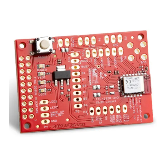
8 Reference design Ophelia-I was tested on the corresponding Ophelia-I evaluation board. Complete layout and schematic information can be found in the manual of the Ophelia-I evaluation board. The reference design is the same for the Proteus-e and Ophelia-I radio mod- ules. -
Page 28: Ev-Board
8.1 EV-Board 8.1.1 Schematic Figure 16: Reference design: Schematic Ophelia-I reference manual version 1.0 © January 2022 www.we-online.com/wireless-connectivity... -
Page 29: Layout
8.1.2 Layout no metal antenna NO METAL 12.5mm PCB edge Figure 17: Reference design: Layout Ophelia-I reference manual version 1.0 © January 2022 www.we-online.com/wireless-connectivity... -
Page 30: Manufacturing Information
PCB layout the optimal soldering profile must be adjusted and verified. Other soldering methods (e.g. vapor phase) have not been verified and have to be validated by the customer at their own risk. Rework is not recommended. Ophelia-I reference manual version 1.0 © January 2022 www.we-online.com/wireless-connectivity... -
Page 31: Cleaning
Shrinking could lead to an incomplete seal, allowing contaminants into the component. Expansion could damage components. We recommend a manual inspection after potting to avoid these effects. Ophelia-I reference manual version 1.0 © January 2022 www.we-online.com/wireless-connectivity... -
Page 32: Other Notations
It is your duty to ensure that the product is allowed to be used in the destination country and within the required environment. Usage of the product can be dangerous and must be tested and verified by the end user. Be especially careful of: Ophelia-I reference manual version 1.0 © January 2022 www.we-online.com/wireless-connectivity... - Page 33 Thebe-II, generate a high amount of warmth while transmitting. The manufacturer of the end device must take care of po- tentially necessary actions for his application. Ophelia-I reference manual version 1.0 © January 2022 www.we-online.com/wireless-connectivity...
-
Page 34: Physical Specifications
Table 15: Weight 10.3 Light sensitivity Inside the Ophelia-I a light sensitive WLCSP package is used. This package is sensitive to visible and near infrared light. As the chip is not completely shielded on the sides, any mounting without enclosure could lead to malfunction. This should be taken into account when designing an enclosure for the end device. -
Page 35: Module Drawing
10.4 Module drawing 9,0 ±0,2 Figure 19: Module dimensions [mm] Ophelia-I reference manual version 1.0 © January 2022 www.we-online.com/wireless-connectivity... -
Page 36: Footprint We
/10 should be kept (see figure 20 ). Even though metal parts would influence the characteristic of the antenna, but the direct influence and matching keep an acceptable level. Ophelia-I reference manual version 1.0 © January 2022 www.we-online.com/wireless-connectivity... -
Page 37: Marking
Date code, 4 digits 2103 = week 03 in year 2021, 2216 = week 16 in year 2022 Firmware version, 3 digits V3.2 = 302, V5.13 = 513 Table 16: Lot number details Ophelia-I reference manual version 1.0 © January 2022 www.we-online.com/wireless-connectivity... -
Page 38: Information For Explosion Protection
• The total amount of capacitance of all capacitors is 6.8 µF. • The total amount of inductance of all inductors is 10.009 µH. • A DC/DC regulator is included in the chip set and used to obtain low power functionality. Ophelia-I reference manual version 1.0 © January 2022 www.we-online.com/wireless-connectivity... -
Page 39: References
13 References [1] Nordic Semiconductor. Nordic nRF52805 resources. https://www.nordicsemi.com/ products/nrf52805 . https://www.we-online.com/catalog/en/WIRL_ACCE_ [2] Würth Elektronik. Himalia. 2600130021 . [3] Würth Elektronik. Proteus-e user manual. https://www.we-online.de/katalog/de/ manual/2612011024000 . Ophelia-I reference manual version 1.0 © January 2022 www.we-online.com/wireless-connectivity... -
Page 40: Important Notes
In this case, the field sales engineer or the internal sales person in charge should be contacted who will be happy to support in this matter. Ophelia-I reference manual version 1.0 © January 2022 www.we-online.com/wireless-connectivity... -
Page 41: Product Improvements
Unless otherwise agreed in individual contracts, all orders are subject to the current ver- sion of the "General Terms and Conditions of Würth Elektronik eiSos Group", last version available at www.we-online.com. Ophelia-I reference manual version 1.0 © January 2022 www.we-online.com/wireless-connectivity... -
Page 42: Legal Notice
This product is not authorized for use in equip- ment where a higher safety standard and reliability standard is especially required or where a failure of the product is reasonably expected to cause severe personal injury or death, Ophelia-I reference manual version 1.0 © January 2022 www.we-online.com/wireless-connectivity... - Page 43 By using Würth Elektronik eiSos GmbH & Co. KG products, the customer agrees to these terms and conditions. Ophelia-I reference manual version 1.0 © January 2022 www.we-online.com/wireless-connectivity...
-
Page 44: License Terms
You shall inform Würth Elektronik eiSos about the intent of such usage before design-in stage. In certain customer applications requiring a very high level of safety and in which the malfunction or failure of an electronic component could endanger human life or Ophelia-I reference manual version 1.0 © January 2022 www.we-online.com/wireless-connectivity... -
Page 45: Ownership
Any liability not expressly provided by Würth Elektronik eiSos shall be disclaimed. You agree to hold us harmless from any third-party claims related to your usage of the Würth Elektronik eiSos’ products with the incorporated Firmware, software and source code. Würth Ophelia-I reference manual version 1.0 © January 2022 www.we-online.com/wireless-connectivity... -
Page 46: Applicable Law And Jurisdiction
By ordering a wireless connectivity product, you accept this license terms in all terms. Ophelia-I reference manual version 1.0 © January 2022 www.we-online.com/wireless-connectivity... - Page 47 List of Figures Ophelia-I ........
- Page 48 more than you expect Monitoring Automated Meter Internet & Control Reading of Things Contact: Würth Elektronik eiSos GmbH & Co. KG Division Wireless Connectivity & Sensors Max-Eyth-Straße 1 74638 Waldenburg Germany Tel.: +49 651 99355-0 Fax.: +49 651 99355-69 www.we-online.com/wireless-connectivity...
Need help?
Do you have a question about the OPHELIA-I and is the answer not in the manual?
Questions and answers