
Subscribe to Our Youtube Channel
Related Manuals for GFA ST 60.15-50,00


Summary of Contents for GFA ST 60.15-50,00
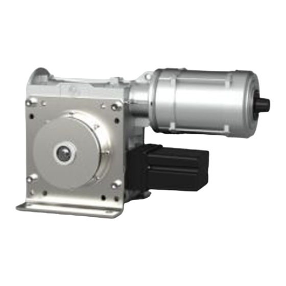
- Page 1 Installation Instructions ELEKTROMAT ST 60.15-50,00 Model: 10003340 00005 -en- Status: 25.11.2021...
- Page 2 GfA ELEKTROMATEN GmbH & Co. KG Wiesenstraße 81 D-40549 Düsseldorf www.gfa-elektromaten.de info@gfa-elektromaten.de...
-
Page 3: Table Of Contents
Table of contents General safety information ....................4 Technical data ........................ 6 Mechanical installation ....................8 Electrical installation ..................... 12 Motor connection ......................13 Limit switch connection ....................13 ... -
Page 4: General Safety Information
The safe operation of the product can only be ensured if it is used as specified. Follow the installation instructions. Observe all specifications, especially warnings, when installing the product in the overall system. GfA is not liable for damage resulting from non-observance of the installation instructions. The resulting overall system must be reassessed for its safety in accordance with applicable standards and directives (e.g. - Page 5 Warning - Failure to follow these installation instructions may result in severe injury or death. Please read these instructions before using the product. Keep these instructions handy. Include these instructions when passing on the product to third parties. Warning - Danger from improper use of the product! ...
-
Page 6: Technical Data
2 Technical data Designation Unit Output speed Output torque 600 (500) Output / hollow shaft 50,00 Series SG 115R Limit switch range (maximum revolutions of the output / hollow shaft) Supply voltage 3N~ 400 Operating current 4,20 Operating frequency Power factor cos φ 0,59 Safety circuit Degree of protection... - Page 7 If the magnetic brake will be continuously supplied the drive can be fitted into areas down to a -20°C ambient temperature.
-
Page 8: Mechanical Installation
3 Mechanical installation Requirements The permissible loads on walls, mountings, connection and transmission elements must not be exceeded even for maximum holding or locking torque (▶ observe technical data). Connection elements ▶ Use self-locking ▶ Use a screw that ▶ Use adequately connection elements with precisely fits the hole. - Page 9 Mounting 4 boreholes are provided for mounting. BAGAD0 4 3 0 1 _Z0 0 2...
- Page 10 Installation The following descriptions refer to a door which is not further defined. The door manufacturer's specifications must also be observed. Warning – Injury or danger to life possible! Use a lifting device with sufficient load-carrying capacity for installation tasks. ...
- Page 11 Warning – Injury or danger to life possible! Disconnect the electrical voltage for the setting of the slipping clutch. ▶ The slipping clutch acts as an overload BAGAE4 3 0 3 _Z0 0 2 protection. The factory setting for the tightening torque is 24Nm (ST 60) or 30Nm (ST 80).
-
Page 12: Electrical Installation
4 Electrical installation Warning - Danger to life from electric current! Switch the mains OFF and check that the cables are de-energised Observe the applicable regulations and standards Make the electrical connection according to standard Use suitable tools Performing electrical installation Remove the cover. -
Page 13: Motor Connection
5 Motor connection Half-wave rectifier Motor Magnetic brake 6 Limit switch connection Thermal contact... -
Page 14: Completing Commissioning / Inspection
7 Completing commissioning / inspection Check the following components and then install all covers. Gearbox Check the drive unit for loss of oil (a few drops can be neglected). Protect the output-shaft permanently against corrosion. Mounting Check that all connection elements (consoles, torque mounts, screws, locking rings, etc.) are secure and in proper condition. - Page 15 Brake Warning - Potential injury or danger to life! Carry out a brake test. Overrun depends on the door and its equipment. The specifications of the door manufacturer must be observed. In an environment that can affect the coefficient of friction of the brake pad (atmosphere with oil, solvents, detergents, etc.), class of protection IP65i must be adopted.
-
Page 16: Disposal
Dispose of old devices properly according to local legal regulations. Return old devices to the return and collection systems available. You can also return GfA products free of charge. Please apply enough postage to the package and mark it as "old devices". -
Page 17: Declaration Of Incorporation / Declaration Of Conformity
EMC Directive 2014/30/EU within the meaning of RoHS Directive 2011/65/EU The following requirements from Appendix I of GfA ELEKTROMATEN GmbH & Co. KG the Machinery Directive 2006/42/EC are met: declare under our sole responsibility that the 1.1.2, 1.1.3, 1.1.5, 1.2.2, 1.2.3, 1.2.6, 1.3.2,...
Need help?
Do you have a question about the ST 60.15-50,00 and is the answer not in the manual?
Questions and answers