Vanderbilt ACTpro-120 Installation And Configuration Instructions
Hide thumbs
Also See for ACTpro-120:
- Installation and operating instructions manual (12 pages) ,
- Installation and operating instructions manual (25 pages)

Related Manuals for Vanderbilt ACTpro-120


Summary of Contents for Vanderbilt ACTpro-120
- Page 1 ACTpro-120 Installation and Configuration Instructions Document ID: A-100661 Edition date: 29.06.2020...
- Page 2 Hereby, Vanderbilt International (IRL) Ltd declares that this equipment type is in compliance with the following EU Directives for CE marking: • Directive 2014/30/EU (Electromagnetic Compatibility Directive) •...
-
Page 3: Table Of Contents
2.2 AC power up 2.3 AC power up (USA) 2.4 Battery insertion 3 Wiring 3.1 Wiring the ACTpro-120 3.2 DIP switch addressing 3.3 Wiring Clock&Data entry and exit readers 3.4 Wiring Wiegand entry and exit readers 3.5 Wiring Door Contact 3.6 Wiring Push Button (PB) -
Page 4: Overview
1 Overview The ACTpro-120 is a door station for a single door, with an integrated 12V 2A DC power supply. It expands any of the existing ACTpro controllers by one door. 1.1 ACTpro-120 features Main relay and AUX relay Supports all ACTpro readers (RFID 125KHz, MIFARE Classic, DESFire EV1) -
Page 5: Psu Output Voltage
ACTpro door station; the second is available to power locks. The full load current is shared between the two outputs. Vanderbilt recommend that a maximum of 1.5A is used to power locks and readers. The remaining 0.5A is used by the door station and battery charging. Total current from both outputs must not exceed 2A. -
Page 6: Ordering Information
ACTpro-120 – Installation and Configuration Instructions Overview Total current available 2000mA Reader x2 200mA Typical mag lock 800mA Total consumption 1500mA Spare capacity 500mA 1.5 Ordering information Controllers Product Code Description ACTpro-1500 V54502-C111-A100 Single door IP controller expandable to 32 doors with ACTpro door stations. -
Page 7: Installation
2 Installation The ACTpro-120 door station is for indoor installation only and must be installed as permanently connected equipment. An external AC disconnect device must be fitted. Before installation ensure that the AC supply to the ACTpro-120 door station is disconnected. -
Page 8: Ac Power Up (Usa)
ACTpro-120 – Installation and Configuration Instructions Installation 2.3 AC power up (USA) 1. Attach a correctly rated AC cable and fasten using the cable tie. 2. Use an approved external AC disconnect device. 3. Apply AC power. Check the AC OK LED is on and measure the +12V output. -
Page 9: Wiring
3 Wiring This section describes the following. 3.1 Wiring the ACTpro-120 3.2 DIP switch addressing 3.3 Wiring Clock&Data entry and exit readers 3.4 Wiring Wiegand entry and exit readers 3.5 Wiring Door Contact 3.6 Wiring Push Button (PB) 3.7 Break Glass monitoring only 3.1 Wiring the ACTpro-120... -
Page 10: Dip Switch Addressing
ACTpro-120 – Installation and Configuration Instructions Wiring 3.2 DIP switch addressing The first cell in each table row indicates the required address; the remaining cells in the row show the required placement of each DIP switch to configure that address. -
Page 11: Wiring Clock&Data Entry And Exit Readers
ACTpro-120 – Installation and Configuration Instructions Wiring 3.3 Wiring Clock&Data entry and exit readers For Clock&Data readers, wire exit readers in parallel with entry readers, but leave the sense line unconnected for exit readers. Max length: 100m with 12V DC Cable: 8 core screened Belden 9504 (24 AWG) or equivalent. -
Page 12: Wiring Wiegand Entry And Exit Readers
ACTpro-120 – Installation and Configuration Instructions Wiring Reader Recommended Controller Terminal Wiring colour Signal Information Input PIN Block GREEN Yellow GREEN Green LED control output from the ACTpro controller or door stations. Connect the reader green cable or terminal marked GREEN on the ACTpro controller. -
Page 13: Wiring Door Contact
ACTpro-120 – Installation and Configuration Instructions Wiring 3.4.0.1 Terminal block wiring Reader Recommended Controller Terminal Wiring colour Signal Information Input PIN Block SENSE White SENSE For Entry readers connect the reader SENSE cable or terminal to the SENSE input pin. For Exit readers, do not use this input. -
Page 14: Break Glass Monitoring Only
The break glass monitoring features only monitors the break glass status and does not remove power from the lock. Vanderbilt assumes a double pole break glass unit is used, one pole to disrupt the power to the lock the second pole for monitoring. - Page 15 ACTpro-120 – Installation and Configuration Instructions Wiring Label Description Label Description Relay Break glass monitoring Magnetic lock © Vanderbilt 2020 A-100661 29.06.2020...
-
Page 16: Monitoring
4 Monitoring AC Present The PSU AC PRESENT output is pre-wired to the AC PRESENT input of the ACTpro-120 door station. Output The PSU output voltage level is reported to the ACT Enterprise software and on the web browser. Voltage Tamper The enclosure lid is tamper monitored. -
Page 17: Status Indicators
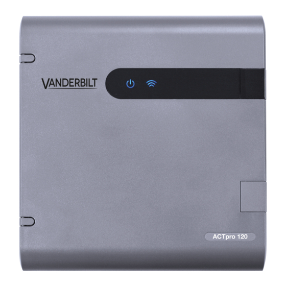
5 Status Indicators Status indicators appear on the front of the ACTpro-120. The meaning of each indicator is described below. (A) Power / System Running This indicates that the ACTpro-120 has power. (B) Communications Constant illumination indicates that the door station is online. -
Page 18: Led Indicators
LED will stay on until the load is fully disconnected. Once the load has been disconnected, remove devices to reduce the current demand below 1.5A. It is important to calculate the power budget adequately. See Power budget on page 5 for more information. © Vanderbilt 2020 A-100661 29.06.2020... - Page 19 © Vanderbilt 2020 Data and design subject to change without notice. Supply subject to availability. Document ID: A-100661 Edition date: 29.06.2020 Issued by Vanderbilt International Ltd. Clonshaugh Business and Technology Park vanderbiltindustries.com Clonshaugh, Dublin D17 KV 84, Ireland @VanderbiltInd Vanderbilt Industries...
Need help?
Do you have a question about the ACTpro-120 and is the answer not in the manual?
Questions and answers