Table of Contents
Advertisement
Quick Links
Technical Manual
Manual Revision 1.08
These instructions are intended as an aid to qualified, licensed installers and
m c
service personnel for proper installation, adjustment and operation of this unit.
Read and understand these instructions thoroughly before attempting installation or
operation. Failure to follow these instructions may result in improper installation,
g k
adjustment, service or maintenance possibly resulting in fire, electrical shock,
carbon monoxide poisoning, explosion, personal injury or property damage.
IOM68
www.engineeredair.com
June 2019
Advertisement
Table of Contents

Related Manuals for EngA CenCon


Summary of Contents for EngA CenCon
- Page 1 Technical Manual Manual Revision 1.08 These instructions are intended as an aid to qualified, licensed installers and service personnel for proper installation, adjustment and operation of this unit. Read and understand these instructions thoroughly before attempting installation or operation. Failure to follow these instructions may result in improper installation, adjustment, service or maintenance possibly resulting in fire, electrical shock, carbon monoxide poisoning, explosion, personal injury or property damage.
- Page 2 This technical manual is intended for technicians and factory personnel already familiar with the operation of Engineered Air equipment, control strategies and combustion setup. The CenCon and expansion modules have been certified by Intertek (ETL) for use with Engineered Air appliances only, evaluated to CSA 22.2 No. 24 Temperature Indicating and Regulating Equipment and UL873 Standard for Safety Temperature Indicating and Regulating Equipment.
- Page 3 CAUTION: The CenCon is specifically programmed for this WARNING: specific appliance. Do not replace with another controller without confirming its program Indicates a hazardous situation that, if not suitability with Engineered Air.
-
Page 4: Table Of Contents
ROOM OR RETURN THERMOSTAT ....19 COOLING ..........11 REMOTE SETPOINT ........ 19 ECONOMIZER ........12 BMS SETPOINT ........19 CENCON ANALOG I/O ......12 ALARM DESCRIPTION ........ 20 CENCON DIGITAL I/O ......12 ALARM RESET ......... 20 HEATING ANALOG I/O ......12 EXPANSION MODULES (XM) ...... - Page 5 Appendix C – Startup Checks ......54 BASIC OPERATION ........39 Appendix D - Service Issues ......54 C-XM TIMING ........... 39 CenCon Specific ........54 TERMINAL DESCRIPTION ......40 READ AND SAVE FEATURES ...... 54 STAGED COMPRESSORS ......41 COMMUNICATION ALARM ......
-
Page 6: General Overview
Notice: There is approximately a 1 minute delay before operation can commence on initial power up. The CenCon has to load parameters and configurations prior to operation. The time varies depending on the complexity of the equipment it is controlling. -
Page 7: Computer Connection
COMPUTER CONNECTION Direct connection may be made to a Windows 10 OS computer or tablet. To gain access to the CenCon testing interface connect using a Cat.5 Ethernet cable to the CenCon, near the top right of the controller. Tablets may require a USB to Ethernet adapter. - Page 8 CenCon INTERFACE SCREENS The layout of the display screen depends on the age and version of the CenCon. The initial release interface display screen example: A second release, similar to the following has been released. Note the tabs along the top bar:...
- Page 9 CenCon The third release screens have been improved for visibility and tablet use. Note the tabs along the top for more screens. The background is black. This image is grey for printing purposes.
-
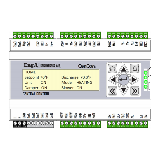
Page 10: Keypad
CenCon KEYPAD The 9 button keypad has been configured to easily manipulate any user variables available for modification. Typically, this would include the temperature setpoint(s) and outside air minimum position. The home button displays the main page. Pressing the alarm button changes the display to the alarm page. -
Page 11: Display Screens
CenCon DISPLAY SCREENS The CenCon display can show a variety of the input and output conditions, in addition to the current operating variables. Additional screens become available as expansion modules (-XM) are added to the system. The display screen saver will automatically go blank after 5 minutes. Pressing any key will reactivate the screen and return to the home page. -
Page 12: Economizer
Discharge 53.8 °F Ambient Air 72.5 °F Return Air 75.8 °F Min. Position 20.0 % Damper 34.5 % CENCON ANALOG I/O ANALOG I/O CENCON 7.2 V 0.0 V 0.0 V 0.0 V 0.0 V 0.0 V 0.0 V HR +/- 0.0 V... -
Page 13: Communication
CenCon COMMUNICATION COMMUNICATION EMS Enabled: ( YES/NO ) Protocol: ( IP / MSTP / NONE ) External MSTP Baud Rate : 38,400 Setpoint Location : ( KEYPAD / EMS ) SETTINGS SETTINGS Load From Factory Load From Default User Save to Default User... -
Page 14: Terminal Description
CenCon TERMINAL DESCRIPTION Terminal Type Name Description Value Power Supply 24 Vac Ground Connect to chassis. LmA B Modbus Internal network BmA,B BACnet BACnet network slave (Future) SmA,B Modbus Modbus network slave (Future) Modulating cooling Chilled water coil valve actuator. 0V=off. -
Page 15: Operation
30 seconds. If the flow proving switch is open, the blower can start normally. After the blower starts, the CenCon needs to see the air switch close (prove) within 30 seconds. If the switch does not close, the low air flow alarm is triggered. -
Page 16: Damper Control
ECONOMIZER Economizer damper control will mix the return and outside air streams to achieve the required discharge air temperature. The CenCon may also be configured to employ an additional mixed air sensor downstream of the mixing dampers. It is possible for the economizer to operate while in heating or cooling mode. While the display will show either heating of cooling, the analog output to the economizer will be active and show a value greater than the minimum position. -
Page 17: Minimum Position
Applications may require economizer damper control ‘by others’. This requires the CenCon to be programmed as a MUA, and uses the FbD (Feedback Damper) input to allow the CenCon to adjust and reset the low limit bypass timer if required during a significant increase in cold outside air. -
Page 18: Gas Fired Heating
Commands to heating expansion modules are done via the internal Modbus network. Refer to the appropriate expansion module section for more information. COOLING The CenCon may control simple fluid based cooling devices (chilled water or glycol) from the auxiliary cooling 0-10Vdc output. Expansion module(s) for mechanical cooling are necessary for staged or modulating mechanical cooling. -
Page 19: Temperature Control
CenCon TEMPERATURE CONTROL The CenCon is a discharge air temperature controller. The discharge setpoint is adjusted from the CenCon display and keypad, between maximum and minimum limits determined by design. There are a number of methods to change, or ‘reset’ the discharge temperature to what the space requires. -
Page 20: Alarm Description
CenCon ALARM DESCRIPTION The last alarm event will be shown on the main page of the CenCon display. A more detailed list can be found by pressing the alarm keypad button . Additional alarms specific to the system are detailed by expansion module type. -
Page 21: Wiring Concerns
NOTICE: For consistency, always wire: Red to LmA Black to LmB. Starting at the CenCon, wiring must be routed in series, or ‘daisy chained’ as shown below. There should never be more than 2 communication wires at any LmA/LmB terminal. -
Page 22: Communication Wire Grounding
CenCon panel ground. All expansion module intermediate drain wires must be twisted together tightly and taped to secure together and isolate from ground. A wire nut or insulated splice connector may also be used. It is important that these must not be grounded anywhere except at the CenCon ground connection. -
Page 23: Expansion Modules (Xm)
CenCon EXPANSION MODULES (XM) The CenCon controller can be connected to any Engineered Air expansion module. The expansion module provides the required wiring terminals for each additional appliance it is controlling. All expansion modules have (2) lights. The Green light is indication of power, and the blinking yellow light is to show communication to the CenCon is connected. -
Page 24: Basic Operation
J-XM will disable the pilot valve. The burner is allowed to operate to maintain the requested discharge air temperature from the CenCon by modulating the control valve and the combustion blower speed. If heating is not required the burner will be disabled and the combustion blower will enter a post purge time, and then shut down. -
Page 25: Terminal Description
CenCon TERMINAL DESCRIPTION Terminal Type Name Description Value Power Supply 24 Vac Ground Connect to chassis. LmA B Modbus Internal Network Compares the ball valve actuator feedback signal to the Feedback Gas 0-10 Vdc demand signal. Modulating ball Modulating gas valve actuator output. -
Page 26: J-Xm / Cd-Xm Timing
CenCon J-XM / CD-XM TIMING Prepurge 60 seconds Post purge 5 minutes Flame failure 15 seconds lockout on ignition control and 60 seconds on burner Pilot opening time 8 seconds Open combustion air 30 seconds proving RPM out of range... -
Page 27: J-Xm Combustion Setup
Return and re-set offset values. CAUTION: Be aware of high discharge temperatures. Power the CenCon, leave the heat switch and fan High limit failure may occur. switch off. Press the UP arrow to enter the Actuator... - Page 28 CenCon NOTICE: Important: remember to un-click the previous gas position button once you have clicked on the next position. Position Near High Fire 90% 3.8 – 4.8 Low Fire 4% 16.8 – 17.3 Near Low Fire 10% 15.0 – 16.0 Medium Fire 1 25% 10.5 –...
-
Page 29: Alarm Description
CenCon ALARM DESCRIPTION Gas valve feedback has power before the FR and SR contact are Gas Valve Wiring energized. Combustion blower feedback exceeds 500 rpm for more than 60 seconds Shorted Air proving when there is no demand. Open Air Proving Combustion blower does not exceed 3000 rpm during purge. -
Page 30: G-Xm
The burner is allowed to operate to maintain the requested discharge air temperature from the CenCon by modulating the gas and air actuators. If heating is not required the burner will be disabled and the combustion blower will enter a post purge time, and then shut down. -
Page 31: G-Xm Timing
CenCon G-XM TIMING Prepurge 60 seconds Post purge 5 minutes Flame failure 15 seconds lockout on ignition control and 60 seconds on burner Pilot opening time 8 seconds Open combustion air 60 seconds proving Improper gas valve wiring 2 seconds... -
Page 32: G-Xm Combustion Setup
Return and re-set offset values. To adjust the high fire air use High Fire Air Offset value. Power the CenCon, leave the heat switch and fan switch off. Follow the sequence noted below exactly and set to the approximate O... - Page 33 CenCon Once the above values have been confirmed and Return to the home screen by pressing the Left set, again press High fire button and allow O arrow key, and then press Save User Settings. levels to stabilize. Press Low Fire, and release the Combustion setup is now complete.
-
Page 34: Alarm Description
CenCon ALARM DESCRIPTION Gas valve actuator feedback is greater or less then the demand . Gas Valve out of range Tolerances and timing depending vary on mode of operation. Air Actuator Feedback Is greater or less then the demand. Tolerances and Air Actuator Out of range timing vary depending on mode of operation. -
Page 35: M-Xm
M-XM will then disable the pilot valve. The burner is allowed to operate to maintain the requested discharge air temperature from the CenCon by modulating the control valve. If heating is not required the burner will be disabled, and then shut down. -
Page 36: Terminal Description
CenCon TERMINAL DESCRIPTION Terminal Type Name Description Value Power Supply 24 Vac Ground Connect to chassis. LmA B Modbus Internal Network Feedback Gas Compares the ball valve actuator feedback signal to the 0-10 Vdc demand signal. Modulating ball Modulating gas valve actuator output. -
Page 37: M-Xm Burner Setup
MAXITROL VALVE Press the UP arrow to enter the actuator Power the CenCon and enable the fan switch. calibration screen. Connect computer to CenCon. Press: Start Setup, then Closed (0%) Set airflow as required. Confirm profile pressure The gas actuator will move to fully closed (90°) -
Page 38: Alarm Description
CenCon ALARM DESCRIPTION Gas valve feedback has no power after 1 minute of enabling the Flame relay Flame Failure output. Gas Valve Wiring Gas valve feedback has power before the FR and SR contact are energized. Received a gas valve feedback within 500ms of activating the Flame relay Flame Relay Wiring output. -
Page 39: C-Xm
CenCon C-XM For direct expansion mechanical cooling operation, including FW, UPW and CU style equipment. BASIC OPERATION For staged compressor operation the C-XM will sequence on and off compressor stages to attempt to maintain the discharge temperature setpoint. As with all staged systems, expect the discharge temperature to fluctuate from setpoint as compressors are turned on and off. -
Page 40: Terminal Description
CenCon TERMINAL DESCRIPTION Terminal Type Name Description Value Power Supply 24Vac Grounded Neutral 24 Vac Ground Connect to chassis. LmA B Modbus Internal Network Modulating Analog output to modulating compressor. 0-10 Vdc compressor Modulating Analog output to variable speed condenser fan. -
Page 41: Staged Compressors
STAGED COMPRESSORS On a call for cooling, the compressors will stage on from 1 to 6. The CenCon cooling programming does not allow for random start, only sequential. Inter-stage and anti-cycle timing is built into the CenCon program and is not adjustable. -
Page 42: H-Xm
CenCon H-XM For control of staged electric heat (LMK and /K) appliances. BASIC OPERATION For staged electric heater operation the H-XM will sequence on and off stages of electric heat to attempt to maintain the discharge temperature setpoint. As with all staged systems, expect the discharge temperature to fluctuate from setpoint as stages are turned on and off. -
Page 43: High Ambient Lockout
CenCon Heating stage #4 Output stage #4 heating, powered from common ‘a’. 24/120 Vac Common to 24/120 Vac Common power relays ‘b’. output set ‘b’ Heating stage #5 Output stage #5 heating, powered from common ‘b’. 24/120 Vac Common to 24/120 Vac Common power relays ‘c’. -
Page 44: S-Xm
CenCon S-XM For control of gas fired SH and SHX humidifiers. BASIC OPERATION The S-XM expansion module controls the operation of SH and SHX series gas fired humidifiers. This includes tank water fill and drain and burner control. On a call for humidification the tank first fills with water, then the burner gas-fired heat is enabled to produce steam. -
Page 45: Operation Notes
CenCon OPERATION NOTES The S-XM can control both the large (120-650) and small (35-90) sizes of humidifiers. The large sizes use a DJ style burner and require the addition of a J-XM and CD-XM expansion module. TERMINAL DESCRIPTION Terminal Type... -
Page 46: Alarm Description
CenCon ALARM DESCRIPTION Drain Sensor Failure Sensor reads <30°F or >212°F for more than 10 seconds. Unexpected hot water reading at drain sensor. Drain temperature has Tank High Pressure Overflow been >110°F after the burner has been on for more than 5 minutes. -
Page 47: Er-Xm
CenCon ER-XM For control of energy recovery systems, including wheels, pipes and plates. BASIC OPERATION On a call for energy recovery, with the enable contact closed, the ER-XM will command the energy recovery method to try and achieve control (heat wheel motor speed, heat pipe tilt actuator, heat plate damper actuator) to discharge setpoint. -
Page 48: Terminal Description
CenCon TERMINAL DESCRIPTION Terminal Type Name Description Value Power Supply 24 Vac Ground Connect to chassis. LmA B Modbus Internal Network Modulating Bypass Damper Modulating output to bypass damper actuator. 0-10 Vdc Demand Drive Motor Modulating output to heat wheel drive motor, heat pipe... -
Page 49: Cd-Xm
CenCon CD-XM TRIAC combustion motor speed drive. The 120V and CB terminals as separated to accept heavy insulation wire from the combustion blower motor. The CD-XM will be mounted in the electrical panel on ‘standard’ equipment. The CD-XM must always be mounted such that the speed sensor wire does not need to be extended, therefore it may be mounted inside the burner cabinet in equipment that has the burner control panel mounted farther away. -
Page 50: P-Xm
The CenCon air pressure monitoring system performs a time weighted calculation based on severity of change to provide some protection against nuisance lock outs from various sources, such as wind gusts. Once the airflow has stabilized, the timer is reset. - Page 51 CenCon Pressure Switch Output contact 24/120 Vac Pressure Sensor Pressure sensor output 0-4”w.c. 0-10 Vdc...
-
Page 52: Appendix A - Thermistor Output Table
CenCon Appendix A - Thermistor Output Table °F °C Ω °F °C Ω °F °C Ω -39.4 323839 28365 45.0 4367 -38.3 300974 26834 46.1 4182 -37.2 279880 25395 47.2 4006 -36.1 260410 24042 48.3 3838 -35.0 242427 22770 49.4 3679 -33.9... -
Page 53: Appendix B - Maxitrol Valve Adjustments
CenCon Appendix B - Maxitrol Valve Adjustments The ES345D-L has a built in regulator for high fire. For M and MR series, adjust high fire with the upstream main regulator. On DJ style burners, the top of the valve is piped into the burner box to provide a pressure to the top of the control valve regulator, extending its operating range and overcoming pressure differences due to the varying combustion blower speed. -
Page 54: Appendix C - Startup Checks
HARD RESET BUTTON Near the edge of the left side face of the CenCon face is a small button which is the hard reset button. If not correctly aligned with the cover plate, it is possible the button could be constantly depressed. In this circumstance the display will be blank, the 4 lights on the right side will not be lit, and the controller will be unresponsive to all commands. -
Page 55: Miscellaneous
CenCon Miscellaneous COMBUSTION ANALYSIS Indirect heaters should be annually checked for quality of combustion. POOR PILOT SENSING Check the condition of the pilot assembly. Check for damaged or dirty ceramics, and the condition of the gasket. Ensure the pilot air tube is free of debris and blockages. Note that on DJ’s and DG’s there is an orifice where the pilot gas line is connected to the pilot air tube. -
Page 56: Speed Sensor - Dj
CenCon SPEED SENSOR – DJ Magnet Magnet Retainer Blower Hall Effect Sensor 1/8” With a digital AC voltmeter, measure the AC volts present on terminals “YS to GS”. When the combustion blower is running there should be 4 to 6 Vac present. If the AC voltage is not present, check the tachometer sensor to magnet gap. -
Page 57: Appendix E - Dj/Dg Fuel Curve Development
CenCon Appendix E – DJ/DG Fuel Curve Development Clocking notes: Correct values for Altitude. Ensure inlet pressure is correct at each stage. All clocked values should be within 5% of the calculated value. Offset values are set by 0.1Vdc increments. If results at low fire are not exact, and either too little or too much gas, use too much so as not to exceed maximum turn down. -
Page 58: Combustion Record - Dj
CenCon Combustion Record - DJ High fire gas and air offsets should be set to zero. Use the PacMan to set air and the appliance regulator to set gas. Serial and Tag# Date Model # Technician Job Name Location Sequence... -
Page 59: Combustion Record - Dg
CenCon Combustion Record - DG High fire gas offset should be set to zero. Use the appliance regulator to set. Serial and Tag# Date Model # Technician Job Name Location Sequence Near High Near Low Medium Medium Name High Fire... -
Page 60: Combustion Record - He
CenCon Combustion Record – HE High fire gas offset should be set to zero. Use the appliance regulator to set. Serial and Tag# Date Model # Technician Job Name Location 1. Set profile pressure drop to 0.7”wc by blocking the discharge. If unable, then evenly block off inlet.
Need help?
Do you have a question about the CenCon and is the answer not in the manual?
Questions and answers