Table of Contents
Advertisement
A
INSTALLATION, OPERATION
AND MAINTENANCE MANUAL
CANADIAN
HEAD OFFICE
AND FACTORY
1401 HASTINGS CRES. SE
CALGARY, ALBERTA
T2G 4C8
Ph: (403) 287-4774
Fx: 888-364-2727
SALES OFFICES ACROSS CANADA AND USA
Retain instructions with unit and maintain in a legible condition.
Please give model number and serial number when contacting
FOR
C-TRAC3
COOLING CONTROLLER
UNIT MODEL NO. _________________
UNIT SERIAL NO. _________________
SERVICED BY: ___________________
TEL. NO: ________________________
USA
HEAD OFFICE
AND FACTORY
rd
32050 W. 83
DESOTO, KANSAS
66018
Ph: (913) 583-3181
Fx: (913) 583-1406
Engineered Air for information and/or parts.
www.engineeredair.com
EASTERN FACTORY
STREET
1175 TWINNEY DRIVE
NEWMARKET, ONTARIO
Ph: (905) 898-1114
Fx: (905) 898-7244
CANADIAN
L3Y 5V7
Jan 13
R5
Advertisement
Table of Contents

Subscribe to Our Youtube Channel
Related Manuals for EngA C-TRAC3


Summary of Contents for EngA C-TRAC3
- Page 1 INSTALLATION, OPERATION AND MAINTENANCE MANUAL C-TRAC3 COOLING CONTROLLER UNIT MODEL NO. _________________ UNIT SERIAL NO. _________________ SERVICED BY: ___________________ TEL. NO: ________________________ CANADIAN CANADIAN HEAD OFFICE HEAD OFFICE EASTERN FACTORY AND FACTORY AND FACTORY 1401 HASTINGS CRES. SE 32050 W. 83...
- Page 2 (403) 287-2590 or Fax (403) 287-4799 or email service@engineeredair.com. To ensure warranty is honored, only a qualified HVAC service person, who has received training on the C-TRAC3, should be employed for service and troubleshooting. If further information is required please contact the nearest Engineered Air office.
-
Page 3: Table Of Contents
C-TRAC3 Table of Contents INTRODUCTION ................................5 STARTUP AND SHUT DOWN ............................. 5 SERVICE SWITCH ................................5 TEMPERATURE CONTROL ..............................6 BASE SETPOINT ................................. 6 SETPOINT RESET ................................6 SETPOINT LIMITS ................................6 MODES OF OPERATION ..............................6 SENSOR #2 ..................................7 MEASURING TEMPERATURE AND SETPOINT ........................ - Page 4 C-TRAC3 4 of 21 Jan 13 R5...
-
Page 5: Introduction
800mA (slow blow). Fuse failure can be checked by having 24Vac across terminals H and N, but the small green light on the face of the C-TRAC3 is not illuminated. There should also be no Vdc reading across V and Z. -
Page 6: Temperature Control
The C-TRAC3 has 3 distinct sequential modes of operation: heating, economizer and cooling. Depending on ambient conditions the C-TRAC3 may start in any of the three modes. Mode change time is five minutes (six minutes from heat to mechanical cooling if there is no economizer). If the C-TRAC3 is unable... -
Page 7: Sensor #2
Table 4 on page 14. OPERATION As the C-TRAC3 is configurable and will vary in its operation unit to unit, it is imperative that the unit function, terminal designation sheet and wiring diagram be reviewed to understand how the control is operating for each particular application. -
Page 8: Ambient Sensing
The fan delay off time can vary from 10s to 2.5 minutes. ECONOMIZER MODE When in economizer mode the C-TRAC3 will mix the warm return air with the cool outside air to try and achieve the required discharge SPC. The C-TRAC3 will modulate the mixing dampers (return, outside and if equipped, exhaust) from fully open to the minimum position setting (expressed as a percentage of outside air). -
Page 9: Minimum Position
If the equipment is employing variable frequency drives to control the fan speed (and program options are selected), a feedback signal of actual speed (10Vdc = 60Hz) is connected to the C-TRAC3. This is to ensure the airflow is adequate to correctly operate and safeguard the equipment. -
Page 10: Ambient Compensation
Heating is allowed to operate if terminal HS is powered (24Vac). The heating is only activated when the C- TRAC3 is in heat or dual mode. The C-TRAC3 has a set of contacts (terminals HE1 and HE2) that will close to enable a heating source, as well as a modulating (0-10Vdc typically) output from terminal HD to control an independent heating controller, SCR, or water/steam valve. -
Page 11: Occupied/Unoccupied
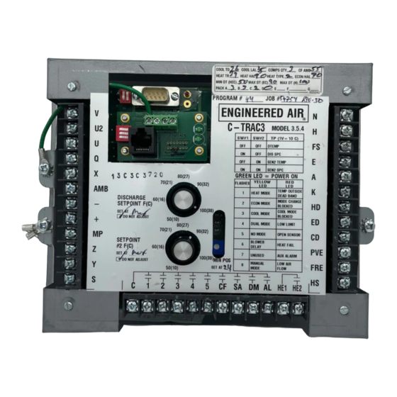
INDICATION AND DIAGNOSTIC LIGHTS On the face of the C-TRAC3 are 3 small LED lights, coloured green, yellow, and red. The green light is to indicate the C-TRAC3 is powered and ready for operation. If power (24Vac) is applied to terminals H and N, and the light is not on, the C-TRAC3 may be faulty and/or the fuse is blown. - Page 12 Ex: multi-zone applications, or de-humidification functions. No Mode will flash when the C-TRAC3 is not allowed to run the heating (HS not powered), cooling (A not powered) or economizer (E powered). This generally occurs because of external controls, ambient lockout, flame failure, etc.
-
Page 13: Low Limit
The C-TRAC3 control will have low limit (freeze) protection included as a standard option. To reset the control after a low limit trip the C-TRAC3 must have the power removed and restored to terminals H and N. This is usually done by turning the unit off at the service switch located inside of the control cabinet. A computer or EMS can also command the C-TRAC3 to reset the air handler from a low limit alarm. -
Page 14: Wiring
Air. WIRING The C-TRAC3 terminals H and N require a minimum 24 Vac, 40 VA class 2 power supply that does not need to be isolated from the rest of the systems components. The C-TRAC3 incorporates an internal ½ wave rectified power supply that has the DC common virtually the same as the AC’s neutral supply (within... -
Page 15: Ems Wiring
The C-TRAC3 is designed to simplify service and troubleshooting. Most equipment failures and problems occur due to sources external to the C-TRAC3, and can easily be traced with a digital multimeter. Advanced troubleshooting may require the use of a computer. -
Page 16: Simulating A Heat/Cool Call
Ohms) and the SPC was at 70°F or warmer, the heat mode should be activated (through the mode timers). As the discharge sensor does not send a signal to the C-TRAC3 that it is satisfied the heat will remain on. -
Page 17: Calibration
C-TRAC3 Calibration Calibration is factory set and cannot be done without a computer using Engineered Air SMC software. Sensor calibration is normally not required, as there are typically external reasons why the sensor is not operating properly, such as inadequate wire size or electrical noise and interference. Contact Engineered Air for assistance. -
Page 18: Sensor Tables
C-TRAC3 SENSOR TABLES Note sensor values on the table below. If the sensor is disconnected, placed at a fixed temperature and the resistance measured, it should be close to the values below. Table 5 SENSOR (purple and blue) Same resistance as TE 6000-960 Set-Point Dialled To 60°F... -
Page 19: Service Notes
C-TRAC3. If it is mounted too far downstream there will be too much lag in the response of the change in temperature, and will cause the actual discharge temperature to hunt up and down. Refer to the equipment Installation Operation and Maintenance manual for mounting location details. - Page 20 Some applications do not require the use of one or both of the setpoint knobs mounted on the face of the C-TRAC3. If not required, the ‘Not Used’ check box will be ticked, with the note ‘Set at Max’ below it.
- Page 21 C-TRAC3 deck temperature setpoint. The adder is selected from a drop down list in the program ranging from 10 to 30°F. 21 of 21 Jan 13 R5...
Need help?
Do you have a question about the C-TRAC3 and is the answer not in the manual?
Questions and answers