Table of Contents
Advertisement
Quick Links
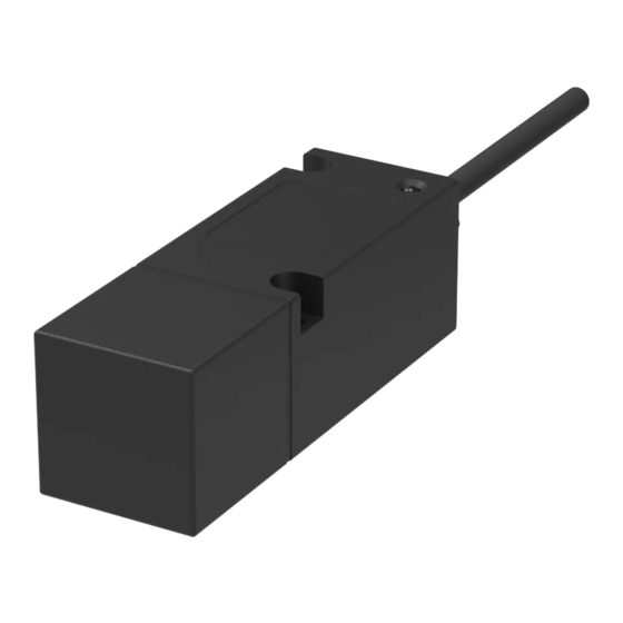
Safety sensor with integrated evaluation
series 117...
Translation of the original operating instructions
Table of contents
1
About these operating instructions .......................................................3
2
Designated use.....................................................................................4
3
Approvals..............................................................................................4
4
Safety instructions ................................................................................4
5
Warning against misuse .......................................................................4
6
Exclusion of liability ..............................................................................4
7
Function................................................................................................4
8
Technical specifications........................................................................4
9
Installation ............................................................................................4
10
Adjustment............................................................................................5
11
Electrical connection.............................................................................5
12
Commissioning .....................................................................................5
13
Maintenance .........................................................................................5
14
Dismantling...........................................................................................5
15
Disposal................................................................................................5
16
Information on the manufacturing date.................................................5
Declaration of conformity ..............................................................................20
1
About these operating instructions
The following standard models are described:
117...
For customer-specific safety sensors with integrated evaluation, the data
sheets can additionally be requested from elobau. The information specified
in the data sheet applies for customer-specific models if this information devi-
ates from the operating instructions.
The person installing the safety sensor is to be provided with the operating in-
structions.
The operating instructions must be kept in a legible condition and in an acces-
sible location.
Meaning of the symbols used:
Warning
Failure to observe this warning can result in faults or malfunc-
tions.
Failure to observe this warning can result in personal injury
and/or damage to the machine.
Information
Indicates available accessories and useful additional informa-
tion.
Actuator
30427102
Rectangular, plastic
30427180
Rectangular, plastic - for increased switching distance
30427182
Rectangular, plastic - for increased switching distance
30420000
Cylindrical, plastic
30420000S
Cylindrical, plastic - for increased switching distance
30420000V
Cylindrical, stainless steel
30420000VS
Cylindrical, stainless steel - for increased switching distance
30420000VH
Cylindrical, stainless steel hygienic design
30420000SH
Cylindrical, stainless steel hygienic design - for increased
switching distance
Art.-Nr./Art. No./Réf./N° art/N° art.: 9010015B01M
ENG
Version: 1.1
Type code safety sensor with integrated evaluation
Performance Level
E
=
PLd
H =
PLe
Supply voltage
1
=
24 V AC/DC
4
=
230 V AC (only with PLd)
1
=
3
=
Plug M12x1 5-pin (only for 24 V AC/DC)
5
=
left side
6
=
front end
7
=
top
2 Designated Use
The safety sensors with integrated evaluation and the appropriate
actuators are used to perform safety-related functions as part of a
complete system or ma-chine, including monitoring of moving,
separating protective devices. The sig-nals generated by the safety
sensor are monitored by the integrated evaluation logic for this
purpose.
The overall control concept in which the safety sensor with
integrated evaluation is incorporated must be validated, for example,
acc. to EN ISO 13849-2.
________________________________________________________
Date: 30.04.2020
[AUXILIARY DEVICE]
E334998
For use only in industrial
machinery NFPA 79
applications
1/11
Advertisement
Table of Contents

Related Manuals for elobau 117 Series


Summary of Contents for elobau 117 Series
-
Page 1: Table Of Contents
For customer-specific safety sensors with integrated evaluation, the data The overall control concept in which the safety sensor with sheets can additionally be requested from elobau. The information specified integrated evaluation is incorporated must be validated, for example, in the data sheet applies for customer-specific models if this information devi- acc. -
Page 2: Technical Specifications
The above-mentioned free zone still applies to the sensor and actuator. Suitable spacer plates for the sensor and actuator are available from elobau under order number 350006. Art.-Nr./Art. No./Réf./N° art/N° art.: 9010015B01M Version: 1.1 2/11... -
Page 3: Electrical Connection
117... 14 Dismantling - The mounting distance between two sensor and actuator systems must be at least 50 mm. The safety sensor is only allowed to be dismantled in a voltage-free state. - Tightly fasten the safety sensor and actuator to the safety device. - Only M5 flat head screws (e.g. - Page 4 Technical specifications Electrical data 117.14E1 117.11H1 117.31H1 117.11E1 24 V AC / DC 24 V AC / DC 24 V AC / DC 230 V AC Operating voltage +/-10% +/-10% +/-10% +/-10% Switching voltage safety 10 V AC / DC 10 V AC / DC 5 V DC 5 V DC...
- Page 5 Electrical data 117.14E1 117.11H1 117.31H1 117.11E1 Max. number of switching operations at 0.5 A 7 x 10 1 x 10 7 x 10 1 x 10 switching current (ohmic load) Max. number of switching operations at 2.5 A 2,5 x 10 2,3 x 10 2,3 x 10 2,5 x 10...
-
Page 6: Connection Type
Environmental data 117.14E1 117.11H1 117.31H1 117.11E1 Relative humidity 5% … 85% Air pressure 860 … 1060 hPa ∆ t 0,5 °C / min max. Mechanical 117.14E1 117.31H1 117.11E1 117.11H1 specifications Housing design - rectangular Housing material PBT GF30 Housing colour: black ... - Page 7 Safety-relevant data 117.14E1 117.11H1 117.31H1 117.11E1 Approval acc. to - DIN EN ISO 13849-1: 2016-06 - DIN EN 60947-5-3: 2014-12 CE mark PL acc. to DIN EN ISO 13849-1: PL d PL e PL d 2016-06 Service life Tm (years) Category acc.
-
Page 8: Control Direction
30427102 117.1... given for types with connection cable. Sensor Ø 5,5 Variant with cable (numbering of the wires) For further information on actuators, please contact elobau for appropriate datasheets. control output safety output Version: 1.1 Date: 30.04.2020 8/11 Art.-Nr./Art. No./Réf./N° art.: 9010015B01M... - Page 9 The circuit diagram is shown in de-energised and unactuated condition (protective door open). The pin assignment is specified for types with connector. Ø5,5 117.3... Variant with connector Sensor sensor control output safety output For further information on actuators, please contact elobau for appropriate datasheets. Version: 1.1 Date: 30.04.2020 9/11 Art.-Nr./Art. No./Réf./N° art.: 9010015B01M...
- Page 10 Ievel. elobau GmbH & Co. KG assumes no liability for the function of the system or for the Ievel of safety achieved. It is our recommendation that the operating instructions should be completely reviewed and followed.
- Page 11 GmbH & Co. KG Zeppelinstraße 44 D-88299 Leutkirch +49-7561-970-0 / www.elobau.com Konformitätserklärung EU- Declaration of Conformity Hiermit erklären wir, dass das nachfolgend aufgeführte Produkt aufgrund der Konzipierung und Bauart den Sicherheits- und Gesundheitsanforderungen der unten genannten EU- Richtlinien entspricht.
Need help?
Do you have a question about the 117 Series and is the answer not in the manual?
Questions and answers