Table of Contents
Advertisement
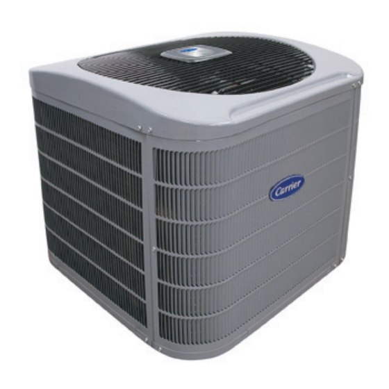
25HCR
COMFORTt SERIES R---22 HEAT PUMPS
SIZES 18 TO 60
1---1/2 TO 5 NOMINAL TONS
Fig. 1 --- 25HCR
NOTE: Read the entire instruction manual before starting the
installation.
Installation Instructions
A05341
TABLE OF CONTENTS
. . . . . . . . . . . . . . . . . . . . . . . . . . . . . .
Step 2 - - Install on Solid Pad
. . . . . . . . . . . . . . . . . . . . . . . . .
. . . . . . . . . . . . . . . . . . . . . . . . . . .
. . . . . . . . . . . . . . . . . . . . . . . . . .
PAGE
. . . . . . . . . . . . . . . . . . . . . . .
. . . . . . . . . . . . .
3 - - 10
. . . . . . . . . . . . . . .
. . . . . . . . . . . . . . . . . . . . . .
. . . . . . . . . . . . . . . . . .
. . . . . . . . . . . . . . . . . . . . . .
3 - - 4
. . . . . . . . . . . . . . . . .
. . . . . . . . . . . . . .
4 - - 6
. . . . . . . . . . . .
6 - - 7
. . . . . . . . . . . . .
. . . . . . . . . . . . . .
7 - - 9
. . . . . . . . . . . . . . . . . . . . . . . . .
. . . . . . . . . . . . . . . . . . . . . .
2
2
3
3
3
3
4
7
7
10
10
10
Advertisement
Table of Contents

Related Manuals for Carrier COMFORT SERIES 25HCR


Summary of Contents for Carrier COMFORT SERIES 25HCR
-
Page 1: Table Of Contents
25HCR COMFORTt SERIES R---22 HEAT PUMPS SIZES 18 TO 60 1---1/2 TO 5 NOMINAL TONS Installation Instructions Fig. 1 --- 25HCR NOTE: Read the entire instruction manual before starting the installation. TABLE OF CONTENTS SAFETY CONSIDERATIONS INSTALLATION RECOMMENDATIONS INSTALLATION ......Step 1 - - Check Equipment &... -
Page 2: Safety Considerations
SAFETY CONSIDERATIONS Improper installation, adjustment, maintenance, or use can cause explosion, fire, electrical shock, or other conditions which may cause death, personal injury, or property damage. Consult a qualified installer, service agency, or your distributor or branch for information or assistance. The qualified installer or agency must use factory- -authorized kits or accessories when modifying this product. -
Page 3: Installation
INSTALLATION STEP 1 —Check Equipment and Job Site Unpack Unit Move to final location. Remove carton taking care not to damage unit. Inspect Equipment File claim with shipping company prior to installation if shipment is damaged or incomplete. Locate unit rating plate on unit corner panel. -
Page 4: Step 6 -Check Defrost Thermostat
10 O'CLOCK 2 O'CLOCK SENSING BULB STRAP SUCTION TUBE 8 O'CLOCK ⁄ IN. OD & SMALLER LARGER THAN Fig. 4 --- Position of Sensing Bulb Replacing TXV on Puron Indoor Coil 1. Pump system down to 2 psig and recover refrigerant. 2. - Page 5 Outdoor units may be connected to indoor section using accessory tubing package or field- -supplied refrigerant grade tubing of correct size and condition. For tubing requirements beyond 80 ft., substantial capacity and performance losses can occur. Following the recommendations in the Application Guideline and Service Manual- -Residential Split- -System Air Conditioners and Heat Pumps will reduce these losses.
-
Page 6: Step 8 -Make Electrical Connections
IMPORTANT: Check to be certain factory tubing on both indoor and outdoor unit has not shifted during shipment. Ensure tubes are not rubbing against each other or any sheet metal. Pay close attention to feeder tubes, makings sure wire ties on feeder tubes are secure and tight. -
Page 7: Step 9 -Compressor Crankcase Heater
Connect Control Wiring Route 24v control wires through control wiring grommet and connect leads to control wiring. See Thermostat Installation Instructions for wiring specific unit combinations. (See Fig. 9.) Use No. 18 AWG color- -coded, insulated (35°C minimum) wire. If thermostat is located more than 100 ft. from unit, as measured along the control voltage wires, use No. - Page 8 HP THERMOSTAT 24 VAC HOT 24 VAC COM HEAT STAGE 2 COOL/HEAT STAGE 1 INDOOR FAN RVS COOLING EMERGENCY HEAT LEGEND 24-V FACTORY WIRING 24-V FIELD WIRING FIELD SPLICE CONNECTION OUTDOOR THERMOSTAT EMERGENCY HEAT RELAY SUPPLEMENTAL HEAT RELAY Fig. 9 --- Generic Wiring Diagrams (See Thermostat Installation Instructions for specific unit combinations) Speedup Quiet...
- Page 9 Sequence of Operation NOTE: Defrost control board is equipped with 5 minute lockout timer that is initiated upon any interruption of power. Turn on power to indoor and outdoor units. Transformer is energized. Cooling On a call for cooling, thermostat makes circuits R- -O, R- -Y, and R- -G.
-
Page 10: Step 12 -Check Charge
5. Fill out Dealer Installation Checklist and place in customer file. Copyright 2006 Carrier Corp. S 7310 W. Morris St. S Indianapolis, IN 46231 Manufacturer reserves the right to change, at any time, specifications and designs without notice and without obligations.
Need help?
Do you have a question about the COMFORT SERIES 25HCR and is the answer not in the manual?
Questions and answers