Advertisement
Quick Links
Document No.:KE-2010-04
Operation Manual
For
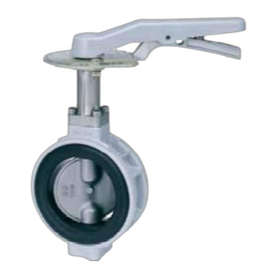
XJ TYPE BUTTERFLY VALVE
(WAFER TYPE)
Thank you for having chosen KITZ products.
For safe and trouble-free function and performance of the
product, make sure to read and understand all items of this
manual before valve mounting and operation.
Keep this manual in a convenient place for your valve operators'
easy access.
Advertisement

Subscribe to Our Youtube Channel
Related Manuals for Kitz XJ


Summary of Contents for Kitz XJ
- Page 1 Operation Manual XJ TYPE BUTTERFLY VALVE (WAFER TYPE) Thank you for having chosen KITZ products. For safe and trouble-free function and performance of the product, make sure to read and understand all items of this manual before valve mounting and operation.
- Page 2 Document No.:KE-2010-04 This manual applies to the KITZ manual XJ type butterfly valve of wafer type. For electric or pneumatic valve operation, refer to the operation manual of relevant valve actuators prepared by the manufacturers. CAUTION AND WARNING To ensure safe and trouble-free function and performance of the product, please read all items of this manual before handling, mounting and operation of the units.
-
Page 3: Table Of Contents
Document No.:KE-2010-04 C O N T E N T S Sheet Ⅰ Construction and Design Features ················································· 1 Ⅱ Valve Operation Device ······································································ 6 Ⅲ Transportation and Storage of Valves·········································· 9 Ⅳ Valve Installation ··················································································· 12 Ⅴ Valve Operation ····················································································· 16 Ⅵ... - Page 4 Document No.:KE-2010-04 Sheet:1/40 CHAPTER Ⅰ Construction and Design Features...
-
Page 5: Ⅰ Construction And Design Features
1.2 90 rotation of the stem opens and closes the valve. 1.3 Butterfly valve is serviceable in fully open, closed and intermediate position for volume control. 1.4 XJ type butterfly valve has center drive mechanism. 1.5 The bi-directional flow is available for butterfly valve. - Page 6 Document No.:KE-2010-04 Sheet:3/40 Ⅰ Construction and Design Features 2. General Feature 2.1 Selectable Neck Design Neck design can be selected from 2 types of long and short as required. 2.2 Interchangeability to JIS Products It complies with JIS B 2032 standardized for butterfly valve. It should be interchangeable to the JIS standard existing butterfly valve.
- Page 7 Document No.:KE-2010-04 Sheet:4/40 Ⅰ Construction and Design Features [S Shape Valve Disc] Spherical disc and it contacts the seat internal evenly 3. Valve Specification and Pressure-Temperature Rating 3.1 Valve Specification 3.1.1 Maximum allowable pressure: 1.0 MPa 3.1.2 Service temperature range: from 20C to +120C (See PT chart for more details) 3.1.3...
- Page 8 Document No.:KE-2010-04 Sheet:5/40 Ⅰ Construction and Design Features 4. Size and Number of Mounting Bolt and Nut JIS 10K Valve Size Length (L) Nominal Size inch 11/2 Hexagonal Bolt and Nut (L=mm) 21/2 5. Minimum Inside Diameter of Applicable Pipes Never apply the pipes with smaller inside diameter than the figures shown in the following table.
-
Page 9: Valve Operation Device
Document No.:KE-2010-04 Sheet:6/40 CHAPTER Ⅱ Valve Operation Device... - Page 10 Document No.:KE-2010-04 Sheet:7/40 Ⅱ Valve Operation Device Lever Handle Type 1.1 The lever handle is directly mounted on the valve. 1.2 Turning the lever handle 90 clockwise will close the valve, and turning the lever handle 90 counterclockwise will open the valve. OPEN CLOSE Fluid Flow Direction...
- Page 11 Document No.:KE-2010-04 Sheet:8/40 Ⅱ Valve Operation Device Worm Gear Type 2. 1 The worm gear operation device is mounted on the valve. 2. 2 According to the letter or arrow on the hand wheel, turning the hand wheel clockwise will close the valve, and turning the hand wheel counterclockwise will open the valve.
- Page 12 Document No.:KE-2010-04 Sheet:9/40 CHAPTER Ⅲ Transportation and Storage of Valves...
-
Page 13: Ⅲ Transportation And Storage Of Valves
Document No.:KE-2010-04 Sheet:10/40 Ⅲ Transportation and Storage of Valves Transportation of Valves 1.1 Caution for safety ● Keep off the valve lifting area to prevent personal injury caused by unsecured valves when transporting the valve by lifting. ● Take care not to damage the valve painting surfaces during transportation, which may subsequently cause corrosion and get the valve rusty. - Page 14 Document No.:KE-2010-04 Sheet:11/40 Ⅲ Transportation and Storage of Valves Storage 2.1 Caution for safety ● DO NOT store valves in the corrosive environment; otherwise, it may cause corrosion on threaded portions of valves. ● DO NOT drop or shake the valves during storage and DO NOT apply any heavy load;...
-
Page 15: Valve Installation
Document No.:KE-2010-04 Sheet:12/40 CHAPTER Ⅳ Valve Installation... - Page 16 Document No.:KE-2010-04 Sheet:13/40 Ⅳ Valve Installation Cautions for Installation ● Check the valve specifications with the catalogs and/or attached nameplate. The substantial part and seat materials determine the characteristic of service fluid and service range of pressure and temperature. Services beyond the valve specifications will cause the leakage problem or other accidents.
- Page 17 Document No.:KE-2010-04 Sheet:14/40 Ⅳ Valve Installation Cautions for Piping ● NEVER use the flange gasket for piping, which may cause the leakage. ● DO NOT forcibly tuck the valve into too narrow space between pipes when piping, which may cause the deformation of the rubber seat and the leakage. ●...
- Page 18 Document No.:KE-2010-04 Sheet:15/40 Ⅳ Valve Installation Valve Mounting 3. 1 Set jack bolts to adjust the dimension between pipe flanges as required. The dimension between pipe flanges must be 6 to 10mm wider than the dimension between the valve faces for installation. 3.
-
Page 19: Valve Operation
Document No.:KE-2010-04 Sheet:16/40 CHAPTER Ⅴ Valve Operation... - Page 20 ● To operate the valve, avoid the use of special tools such as pipes or wrenches, which may damage the valves. ● When the valve is to be used with an opening position less than 30°, contact KITZ or its distributor for technical advises. Operation 2. 1 Lever Handle Type Turning the lever handle 90°...
- Page 21 Document No.:KE-2010-04 Sheet:18/40 Ⅴ Valve Operation Daily Inspection The maintenance of the valves is performed at daily inspection and inspection during operation. The below is the list of inspection items. Items to be Areas to be Inspection Countermeasures inspected inspected Method Visual check Retighten flange bolts.
- Page 22 Document No.:KE-2010-04 Sheet:19/40 Ⅴ Valve Operation Countermeasures ● Wear the protective items such as eye protectors, gloves, and working boots. ● Take some safety measures for maintenance of valves which handle toxic, flammable or corrosive fluid. ● Reduce the line pressure to the atmospheric level before retightening of flange bolts and nuts.
-
Page 23: Periodic Inspection
Document No.:KE-2010-04 Sheet:20/40 CHAPTER Ⅵ Periodic Inspection... - Page 24 Document No.:KE-2010-04 Sheet:21/40 Ⅵ Periodic Inspection Periodic Inspection 1.1 Carry out periodic inspection about once a year with the valve on pipes. 1.2 Make sure that valve is operating smoothly and functioning sufficiently without threatening safety. 1.3 Refer to Section V “Daily Inspection” for the inspection items and inspection methods. 1.4 Carry out the periodic inspection of valves which are not operated for long period or not daily inspected.
- Page 25 Document No.:KE-2010-04 Sheet:22/40 Ⅵ Periodic Inspection Maintenance and Inspection. When piping facilities where the valves are installed are to be set open for periodic maintenance and inspection, carry out the seat and external leakage test and operation test as required. If any signs of seat/external leakage are found, overhaul and maker sure it is satisfactory.
- Page 26 Document No.:KE-2010-04 Sheet:23/40 Ⅵ Periodic Inspection 2.3 Test and Inspection The following is the main items for test and inspection. 2.3.1 Operation test (1) Operate the valve smoothly by lever handle or worm gear handle without galling or sticking. (2) Connect the stem firmly with the disc. (3) In fully open position, the disc must be parallel to the fluid flow.
- Page 27 Document No.:KE-2010-04 Sheet:24/40 CHAPTER Ⅶ Disassembly and Reassembly of Valves...
-
Page 28: Ⅶ Disassembly And Reassembly Of Valves
Document No.:KE-2010-04 Sheet:25/40 Ⅶ Disassembly and Reassembly of Valves Disassembly 1.1 Cautions for Safety ● Operator should take an appropriate caution for not being exposed to the fluid or not to catch fire. ● Wear the protective items such as eye protectors, gloves and working boots. ●... - Page 29 Document No.:KE-2010-04 Sheet:26/40 Ⅶ Disassembly and Reassembly of Valves 1.3 Reassembling Instruction Dismantle the valves from the pipes before rearrangement. ● DO NOT dismantle the neck (stand) on pressing. The stem may blow out if dismantled on pressing. Figure 1 ●...
- Page 30 Document No.:KE-2010-04 Sheet:27/40 Ⅶ Disassembly and Reassembly of Valves 1.4 Disassembly (Dismantling the operation device) 1.4.1 Gear Operation Device ① Fully close the valve. ② Match-mark the gear unit (102), stand (61), and body (1) in order to smooth the reassembly and avoid misplacing the direction of parts.
- Page 31 Document No.:KE-2010-04 Sheet:28/40 Ⅶ Disassembly and Reassembly of Valves Disassembly (40A) 2.1.1 Remove the stand mounting bolt (63) and stand (61). 2.1.2 Pull out the stem (3) from the body (1). 2.1.3 Remove the disc (4) from the body (1). 2.1.4 Remove the rubber seat (106) by inserting a flat blade screwdriver between the body (1) and seat to make the space and putting the hand into that space to take out the rubber seat (106).
- Page 32 Document No.:KE-2010-04 Sheet:29/40 Ⅶ Disassembly and Reassembly of Valves 1.7 Disassembly (250A~300A) 1.7.1 Remove the stand mounting bolt (63) and stand (61). (In case of Short-Neck type, it is unnecessary to remove them without a stand. ) 1.7.2 Remove the gland plate bolt (36) and gland plate (144). 1.7.3 Pull out the stem (3) from the body (1).
- Page 33 Document No.:KE-2010-04 Sheet:30/40 Ⅶ Disassembly and Reassembly of Valves 2. Reassembly 2.1 Cautions for safety ● Wear the protective items such as eye protectors, gloves and working boots. ● Take not to catch fire during reassembly. ● Take care not to pinch hands or fingers during reassembly. ●...
- Page 34 Document No.:KE-2010-04 Sheet:31/40 Ⅶ Disassembly and Reassembly of Valves 2.3 Assembly (40A) 2.3.1 Assemble the O-ring (45C) to the bearing (67), apply the liquid packing (ThreeBond 1215) around the bearing and assemble into the body (1). 2.3.2 Fix the upper side of the body (1) done up. Curve as concave, holding on the bottom of the rubber seat (106) by the thumb, fit the rubber seat (106) into the body (1) from the upper side to the bottom side.
- Page 35 Document No.:KE-2010-04 Sheet:32/40 Ⅶ Disassembly and Reassembly of Valves 2.4.3 Place the hole located at the bottom of the rubber seat (106) into the bottom stem (103) then assemble into the body (1). After completing the rubber seat (106) assembly, pull out the bottom stem (103).
- Page 36 Document No.:KE-2010-04 Sheet:33/40 Ⅶ Disassembly and Reassembly of Valves 2.5 Assembly (250A~300A) Body 2.5.1 Insert the bottom stem (103) into the body (1) beforehand as shown in the figure in order to use as a guide at assembly of the rubber seat (106) to the body (1).
- Page 37 Document No.:KE-2010-04 Sheet:34/40 Ⅶ Disassembly and Reassembly of Valves 2.5.9 Assemble the bottom stem (103) and O-ring (45B) and the stem bearing (67B). 2.5.10 Insert the bottom stem (103) and tighten the end plate (147) with end plate bolt (35). At this point, assemble the spring washer (145A) to the end plate (147).
- Page 38 Document No.:KE-2010-04 Sheet:35/40 Ⅶ Disassembly and Reassembly of Valves 3.1 Cross-Sectional Assembly Drawing. (Gear Type, 40A) 部番 部 品 名 Body Stem Disc Nameplate O-ring O-ring Snap ring Stand Stand mounting bolt Bearing Thrust bearing Bolt for gear set Gear unit Rubber seat This drawing indicates a typical construction of the valve.
- Page 39 Document No.:KE-2010-04 Sheet:36/40 Ⅶ Disassembly and Reassembly of Valves 3.2 Cross-Sectional Assembly Drawing. (Gear Type, 50A~200A Long-Neck and Lever type 40A~150A) Parts Name Body Stem Disc Nameplate Endplate bolt O-ring O-ring Snap ring Stand Stand mounting bolt Bearing Thrust bearing Bolt for gear set Gear unit Bottom stem...
- Page 40 Document No.:KE-2010-04 Sheet:37/40 Ⅶ Disassembly and Reassembly of Valves 3.3 Cross-Sectional Assembly Drawing. (Gear Type, 250A~300A Long-Neck) Parts Name Body Stem Disc O-ring washer Nameplate Endplate bolt Gland plate bolt O-ring O-ring Stand Stand mounting bolt Stem bearing Stem bearing Stem bearing Bolt for gear set Gear unit...
- Page 41 Document No.:KE-2010-04 Sheet:38/40 Ⅶ Disassembly and Reassembly of Valves 3.4 Cross-Sectional Assembly Drawing. (Gear Type, 50A~100A Short-Neck) Parts Name Body Stem Disc Nameplate Endplate bolt O-ring O-ring Snap ring Stand Stand mounting bolt Bearing Thrust bearing Bolt for gear set Gear unit Bottom stem Rubber seat...
- Page 42 Document No.:KE-2010-04 Sheet:39/40 Ⅶ Disassembly and Reassembly of Valves 3.5 Cross-Sectional Assembly Drawing. (Gear Type, 125A~200A Short-Neck) Parts Name Body Stem Disc Nameplate Endplate bolt O-ring O-ring Snap ring Stand Stand mounting bolt Bearing Thrust bearing Hex. Socket set screw Hex.
- Page 43 Document No.:KE-2010-04 Sheet:40/40 Ⅶ Disassembly and Reassembly of Valves 3.6 Cross-Sectional Assembly Drawing. (Gear Type, 250A~300A Short-Neck) Parts Name Body Stem Disc O-ring washer Nameplate Endplate bolt Gland plate bolt O-ring O-ring Stem bearing Stem bearing Bolt for gear set Gear unit Bottom stem Rubber seat...
Need help?
Do you have a question about the XJ and is the answer not in the manual?
Questions and answers