
Related Manuals for Daewoo RD-400 Series


Summary of Contents for Daewoo RD-400 Series
- Page 1 9CD8303000 S/N No. : Service Manual DVD Micro System Mini Component System RD-400 ( ) Series Model: series only DAEWOO DAT CO., LTD. JAN. 2005 FEB. 2004...
-
Page 2: Table Of Contents
Pb OUTPUT DATA WAVEFORM IN COMPONENT OUTPUT Y OUTPUT DATA WAVEFORM IN COMPONENT OUTPUT COMPOSITEOUTPUT DATA WAVEFORM IN MONITOR OUTPUT S-VIDEO OUTPUT DATA WAVEFORM DVD MICRO SYSTEM RD-400 ( 8. INTERNAL BLOCK DIAGRAM OF ICs...24/28 9. BLOCK DIAGRAM...29 10. WIRING DIAGRAM...30 11. SCHEMATIC DIAGRAM...31/35... -
Page 3: Safety Precautions
1. Safety Precautions WARNING: TO PREVENT FIRE OR ELECTRIC SHOCK, DO NOT EXPOSE THIS APPLIANCE TO RAIN OR MOISTURE. CAUTION RISK OF ELECTRIC SHOCKS DO NOT OPEN CAUTION :TO REDUCE THE RISK IF ELECTRIC SHOCK, DO NOT REMOVE COVER (OR BACK). NO USER SERVICEABLE PARTS INSIDE. - Page 4 1. Safety Precautions 13.Outdoor Antenna Grounding - If an outside antenna is connected to the receiver be sure the antenna system is grounded so as to provide some protection against voltage surges and built-up static charges. Article 810 of the National Electrical Code, ANSI/NFPA 70, provides information with regard to proper grounding of the mast and supporting structure, grounding of the lead-in wire to an antenna-dis...
-
Page 5: Specifications
2. Specifications... -
Page 6: Location Of Users Controls
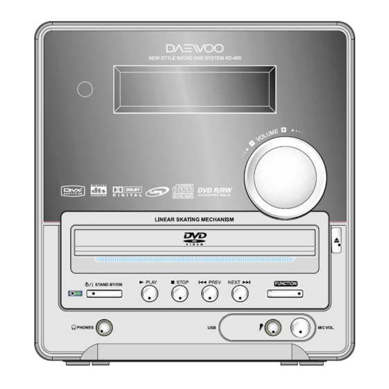
3. Location of Users Controls Front Panel 1. Remote Control Sensor 2. Display 3. DISC TRAY 4. STANDBY/ON button 5. STANDBY/ON LED lamp 6. PHONES jack 7. PLAY ( ) button 8. STOP ( ) button 9 10 9. PREV ( 10. -
Page 7: Rear Panel
3. Location of Users Controls Rear Panel Display 1. DOLBY DIGITAL indicator 2. Pro Logic II indicator 3. DTS indicator 4. TITLE indicator 5. DVD indicator 6. CHAPTER indicator 7. VCD indicator 8. TRACK indicator 9. MP3 indicator 10. SLEEP indicator 11. -
Page 8: Remote Controller
3. Location of Users Controls Remote Controller ENTER 1. STANDBY/ON button 2. OPEN/CLOSE button 3. MUTE button 4. INPUT SELECTOR: DVD button/ TV SYSTEM(PAL/NTSC: DVD only) button 5. INPUT SELECTOR: VIDEO button 6. INPUT SELECTOR: TUNER button 7. FAST REVERSE(FR) ( 8. -
Page 9: Connecting To Equipment
4. Connecting to Equipment Connecting to TV 21-Pin SCART Cable(not included) to 21-pin SCART input terminal on TV SCART Specification : Composite and Component Video output(DVD, Video)Audio L/R Output(DVD only) If the TV or monitor is equipped with an S video input, make the S video connection in addition to the normal video connection. -
Page 10: Connecting To Speaker
4. Connecting to Equipment Connecting to Speaker Before connecting This machine is designed to reproduce optimum sound quality when speakers with the specified impedance below are connected. Please check the following information and choose speakers with appropriate impedance for the connections. -
Page 11: Firmware Upgrade
5. Firmware Upgrade Preparing the Firmware Upgrade 1. Write a disc to update file by PC Writing Program. 2. A size of dummy folder is more than 10M bite. (ex : font_dw, attached picture) 3. Put firmware file in a disc. •... - Page 12 5. Firmware Upgrade Read the disc. 1. Automatically open the door, after read from disc. 2. Take a disc out of a tray Checksum check & Update new firmware. Caution • While updating, if the door opened or closed by touch, or power button is pressed, the Flash Memory will be damaged.
-
Page 13: Trouble Shooting Guide
6. Trouble Shooting Guide Audio Part 1. BASIC OPERATING START Is Standby LED Turn Power on. Is Power on? Does Initial read work? Does It Play? Does It Output Audio? Check Power Supply Circuit. Check Connection CN901, CN951. Check DVD Processor Circuit. IC501 Block. - Page 14 6. Trouble Shooting Guide Front Circuit 1. INITIAL OPERATING START Is Standby LED on? Is Power on? Initial Operation OK. Is Power on? Check Connection CN901/CN951. Check Power Supply. Check OSC waveform of XC501. Check DVD Power Supply Check I2C Line of IC504.
- Page 15 6. Trouble Shooting Guide Audio Part 3. AUDIO Abnormal Audio Abnormal of DVD Function Check if the I2S Output of IC501 is ok? Check if theI2S Input of IC861 is ok? Check if the Output of IC861 is ok? Video Output Funtion Digital Audio Input Funtion...
- Page 16 6. Trouble Shooting Guide Audio Part 3. AUDIO Abnormal Audio Abnormal of Tuner /Video Input Function Check if the Audio output of IC401 is ok? Check if the Audio output of IC421 is ok? 4. AUDIO LINE OUTPUT Abnormal Audio Abnormal of H/P Output Check if the Output of IC811...
- Page 17 6. Trouble Shooting Guide Audio Part 5. AUDIO CONTROL Abnormal Audio Abnormal of Volume Control Check if the data of IC501 is Check if the I2C Waveform of IC841 is ok? 5. AUDIO CONTROL Abnormal Audio Abnormal of Remote Control Check if the data of IC501 is ok?
- Page 18 6. Trouble Shooting Guide Audio Part 6. VIDEO OUTPUT Abnormal VIDEO Abnormal of Component Check if the Output of IC501 is ok? Check the output of Jack is ok? Check Crystal is ok? Replace Cystal, XC501. Check Setup is ok? Setting for RGB Mode.
- Page 19 6. Trouble Shooting Guide Audio Part 6. VIDEO OUTPUT Abnormal VIDEO Abnormal of S-VIDEO Check if the Output of IC501 is ok? Check the output of Jack is ok? Check Crystal is ok? Replace Crystal, XC501. Check Setup is ok? Setting for S-VIDEO Mode.
- Page 20 6. Trouble Shooting Guide Audio Part 6. VIDEO OUTPUT Abnormal VIDEO Abnormal of Composite Check if the Output of IC501 is ok? Check the output of IC481 is ok? Check the output of Jack is ok? Check Crystal is ok? Replace Crystal, XC501.
- Page 21 6. Trouble Shooting Guide Audio Part 7. MECHA CONTROL Abnormal Control Abnormal of Open/Close Check if the data input of IC501 is ok? Check the output of IC303 pin 1,7 is ok? Check VFD data is ok? Replace Front PCB Ass'y. Check Connection CN701.
- Page 22 6. Trouble Shooting Guide Audio Part 7. MECHA CONTROL Abnormal Control Abnormal of Disc Loading Check if the data input of IC501 is ok? Check the output of IC302 is ok? Check VFD data is ok? Replace Front PCB Ass'y. Check Connection CN701.
-
Page 23: Waveforms Of Major Check Point
7. Waveforms of Major Check Method Test Point : DVD Test Disc MDVD-W111 TRACK2 Color Bar • Audio Out Signal Waveform • DAC Output Signal Waveform • Optical Output Audio Data Signal waveform • PWM Output Waveform During Normal Play •... - Page 24 7. Waveforms of Major Check Method Test Point : DVD Test Disc MDVD-W111 TRACK2 Color Bar • Pr Output Data Waveform in Component Output • Pb Output Data Waveform in Component Output • Y Output Data Waveform in Component Output...
- Page 25 7. Waveforms of Major Check Method Test Point : DVD Test Disc MDVD-W111 TRACK2 Color Bar • Composite Output Data Waveform in Monitor Output • S-Video Output Data Waveform...
-
Page 26: Internal Block Diagram Of Ics
8. Internal Block Diagram of ICs • 74HC374 • 74HCU04 • BA6287F • BU4052 COMMON OUT / IN OUT / IN COMMON... - Page 27 8. Internal Block Diagram of ICs • CS4340 • FAN8024DB • LA7952 • LD1117A...
- Page 28 8. Internal Block Diagram of ICs • ES6629FD/ES6698FD • M29W800DB...
- Page 29 8. Internal Block Diagram of ICs PT2314...
- Page 30 8. Internal Block Diagram of ICs • PT6315 • PT8311...
-
Page 31: Block Diagram
9. Block Diagram... -
Page 32: Wiring Diagram
10. Wiring Diagram... -
Page 33: Schematic Diagram
11. Schematic Diagram MPEG Section... -
Page 34: Mpeg Rf Section
11. Schematic Diagram MPEG RF Section... - Page 35 11. Schematic Diagram I/O Section...
-
Page 36: Front Section
11. Schematic Diagram FRONT Section... -
Page 37: Power Section
11. Schematic Diagram POWER Section... -
Page 38: Printed Circuit Diagram
12. Printed Circuit Diagram FRONT [Top View]... - Page 39 12. Printed Circuit Diagram FRONT [Bottom View]...
- Page 40 12. Printed Circuit Diagram MAIN [Top View]...
- Page 41 12. Printed Circuit Diagram MAIN [Bottom View]...
- Page 42 12. Printed Circuit Diagram MPEG [Top View]...
- Page 43 12. Printed Circuit Diagram MPEG [Bottom View]...
-
Page 44: Exploded View And Mechanical Parts List
14. Exploded View and Mechanical Parts List... - Page 45 14. Exploded View and Mechanical Parts List...
- Page 46 PCB MAIN Ass'y [9CDC074900] : RD400 MAIN Loc. Part Code B801 9CD6596500 PCB MAIN CE811 CEXF1E470V C ELECTRO CE812 CEXF1E470V C ELECTRO CE813 CEXF1H339V C ELECTRO CE814 CEXF1H339V C ELECTRO CE815 CEXF1H339V C ELECTRO CE816 CEXF1H339V C ELECTRO CE817 CEXF1E100V C ELECTRO CE821 CEXF1E470V...
- Page 47 Loc. Part Code CM901 HCBK104KBA C CHIP CERA CM902 HCBK104KBA C CHIP CERA CM903 HCBK104KBA C CHIP CERA CM904 HCBK104KBA C CHIP CERA CM907 HCBK104KBA C CHIP CERA CM908 HCBK104KBA C CHIP CERA CW861 9728811800 CONN WAFER CN871 9736407800 CONN PIN CN881 9736407800 CONN PIN...
- Page 48 Loc. Part Code HC872 HCBK222KBA C CHIP CERA HC873 HCQK100JBA C CHIP CERA HC874 HCBK102KBA C CHIP CERA HC875 HCBK102KBA C CHIP CERA HC876 HCQK100JBA C CHIP CERA HC877 HCBK222KBA C CHIP CERA HC878 HCBK104KBA C CHIP CERA HC902 HCBK104KBA C CHIP CERA HC903 HCBK104KBA...
- Page 49 Loc. Part Code HR836 HRFT183JBA R CHIP HR839 HRFT820JBA R CHIP HR841 HRFT102JBA R CHIP HR842 HRFT104JBA R CHIP HR843 HRFT104JBA R CHIP HR844 HRFT562JBA R CHIP HR845 HRFT102JBA R CHIP HR846 HRFT104JBA R CHIP HR847 HRFT104JBA R CHIP HR848 HRFT562JBA R CHIP HR849...
- Page 50 Loc. Part Code IC871 1STK433030 IC POWER IC902 1KIA7812AP IC REGULATOR IC903 1KIA7912AP IC904 1KA278R05- IC REGULATOR IC905 1KIA7805AP IC REGULATOR J871 9736323400 JACK SPEAKER JW801 W581GY7595 WIRE JUMPER JW802 W581GY7595 WIRE JUMPER JW803 W581GY7595 WIRE JUMPER JW804 W581GY7595 WIRE JUMPER JW805 W581GY7595 WIRE JUMPER...
- Page 51 Loc. Part Code JW859 W581GY1005 WIRE JUMPER JW860 W581GY1005 WIRE JUMPER JW861 W581GY1005 WIRE JUMPER JW862 W581GY1005 WIRE JUMPER JW863 W581GY1005 WIRE JUMPER JW864 W581GY1005 WIRE JUMPER JW865 W581GY1005 WIRE JUMPER JW866 W581GY1005 WIRE JUMPER JW867 W581GY6095 WIRE JUMPER JW868 W581GY6095 WIRE JUMPER JW869...
- Page 52 Loc. Part Code CW301 9CD6273500 CONN WAFER CW302 9728810900 CONN WAFER CW303 9728811800 CONN WAFER CW501 9CD6269000 CONN WAFER CW502 9736408600 CONN WAFER CW503 9728811800 CONN WAFER HA501 HRTT8100J R ARRAY CHIP HA502 HRTT8100J R ARRAY CHIP HA503 HRTT8100J R ARRAY CHIP HA504 HRTT8330J R ARRAY CHIP...
- Page 53 Loc. Part Code HC509 HCBK104KBA C CHIP CERA HC510 HCBK104KBA C CHIP CERA HC511 HCBK104KBA C CHIP CERA HC512 HCBK104KBA C CHIP CERA HC513 HCBK104KBA C CHIP CERA HC514 HCBK104KBA C CHIP CERA HC515 HCBK104KBA C CHIP CERA HC516 HCBK104KBA C CHIP CERA HC517 HCBK104KBA...
- Page 54 Loc. Part Code HC578 HCBK104KBA C CHIP CERA HC579 HCBK104KBA C CHIP CERA HC580 HCQK471JBA C CHIP CERA HC581 HCQK471JBA C CHIP CERA HC582 HCQK471JBA C CHIP CERA HC583 HCQK471JBA C CHIP CERA HC584 HCQK471JBA C CHIP CERA HC585 HCQK471JBA C CHIP CERA HD301 DZDS160---...
- Page 55 Loc. Part Code HR329 HRFT103JBA R CHIP HR330 HRFT152JBA R CHIP HR331 HRFT105JBA R CHIP HR340 HRFT102JBA R CHIP HR341 HRFT512JBA R CHIP HR342 HRFT100JBA R CHIP HR343 HRFT100JBA R CHIP HR344 HRFT103JBA R CHIP HR345 HRFT332JBA R CHIP HR346 HRFT104JBA R CHIP HR347...
- Page 56 Loc. Part Code IC302 1FAN8024CD IC303 1BA6287F-- IC304 1TL3472CD- IC501 1ES6698FD- IC MPEG IC502 1L128168A- IC SDRAM IC503 1M29W160EB IC FLASH IC504 1M24C04MN- IC505 1LD1117A33 IC REGULATOR IC506 1LD1117A-R IC REGULATOR IC510 174HC374NS IC511 174HC374NS XC501 5XJ27M000E X-TAL PCB INOUT Ass'y [9CDC075000] : RD400 INOUT Loc.
- Page 57 Loc. Part Code HC455 HCQK101JBA C CHIP CERA HC456 HCBK104KBA C CHIP CERA HC457 HCBK104KBA C CHIP CERA HC458 HCQK101JBA C CHIP CERA HC459 HCQK101JBA C CHIP CERA HC461 HCQK101JBA C CHIP CERA HC462 HCQK101JBA C CHIP CERA HC481 HCBK104KBA C CHIP CERA HC482 HCQK101JBA...
- Page 58 Loc. Part Code HR458 HRFT473JBA R CHIP HR459 HRFT104JBA R CHIP HR460 HRFT750JBA R CHIP HR461 HRFT104JBA R CHIP HR462 HRFT391JBA R CHIP HR463 HRFT473JBA R CHIP HR464 HRFT750JBA R CHIP HR465 HRFT104JBA R CHIP HR466 HRFT391JBA R CHIP HR467 HRFT473JBA R CHIP HR468...
- Page 59 Loc. Part Code JW427 W581GY7595 WIRE JUMPER JW428 W581GY7595 WIRE JUMPER JW429 W581GY7595 WIRE JUMPER JW430 W581GY7595 WIRE JUMPER JW431 W581GY6095 WIRE JUMPER JW432 W581GY12J5 WIRE JUMPER JW433 W581GY12J5 WIRE JUMPER JW434 W581GY12J5 WIRE JUMPER JW435 W581GY12J5 WIRE JUMPER JW436 W581GY1505 WIRE JUMPER JW437...
- Page 60 Loc. Part Code HD702 DZDS160--- DIODE SW CHIP HD703 DZDS160--- DIODE SW CHIP HD704 DZDS160--- DIODE SW CHIP HD705 DZDS160--- DIODE SW CHIP HD706 DZDS160--- DIODE SW CHIP HD707 DZDS160--- DIODE SW CHIP HD751 DZDS160--- DIODE SW CHIP HQ701 TZRC231S-- TR CHIP HQ702 TZRC231S--...
- Page 61 Loc. Part Code JW704 W581GY1505 WIRE JUMPER JW705 W581GY1505 WIRE JUMPER JW706 W581GY1005 WIRE JUMPER JW707 W581GY12J5 WIRE JUMPER JW708 W581GY12J5 WIRE JUMPER JW709 W581GY1505 WIRE JUMPER JW710 W581GY7595 WIRE JUMPER JW711 W581GY6095 WIRE JUMPER JW712 W581GY6095 WIRE JUMPER JW713 W581GY6095 WIRE JUMPER JW714...
- Page 62 Loc. Part Code VR751 5V1503730B VR ROTARY XC701 ZTB455ET3C RESONATOR CERA PCB POWER Ass'y [9CDC075100] : RD400 POWER Loc. Part Code B951 9CD6596800 PCB POWER CD951 9736910800 AC CORD CE951 CEXF1C102V C ELECTRO CN951 9736407600 CONN PIN CW981 9728808400 CONN WAFER D951 DIN4001--- DIODE...
Need help?
Do you have a question about the RD-400 Series and is the answer not in the manual?
Questions and answers