
Related Manuals for Gram Standard Plus


Summary of Contents for Gram Standard Plus
- Page 1 Operating- and servicemanual Gram Standard Plus / Baker Standard 765042138 Rev.001...
-
Page 2: Table Of Contents
Table of contents Distance to wall and ceiling .......................... 3 General description ............................ 4 Electrical connection ............................ 5 General use ................................ 6 Cleaning ................................ 8 Operating the product ............................ 9 Start‐up ................................ 11 Defrost ................................ 11 Keyboard Lock .............................. 11 Changing the temperature .......................... 12 Errors and Alarms ............................ 12 Display of the evaporator sensor reading ....................... 13 HACCP Alarms .............................. 13 Setting of HACCP alarm values ........................ 13 Display of HACCP alarms .......................... 14 Deletion of HACCP alarms .......................... 14 Cleaning of condenser filter .......................... 15 Default factory settings ........................... 15 Access to service parameters .......................... 16 Parameter overview ............................ 17 COMPRESSOR PROTECTION SYSTEM ...................... 18 DEFROSTING ..............................19 ... -
Page 3: Distance To Wall And Ceiling
Distance to wall and ceiling The product should be placed as close as possible up against the back wall. For products with a heating element in the tray on the cabinet backside, however max. 75 mm from the wall. (K & M models) There must always be 300 mm of free space above the product, to ensure that the heat from the condenser can be led away. -
Page 4: General Description
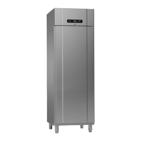
General description Condenser with air filter Compressor Front panel Display Gasket Door Air intake Air distribution plate Shelves for storage 765042138 Rev.001... -
Page 5: Electrical Connection
If it is a product connected to an external compressor unit, it must be examined by the company who has connected the product to the unit. Outside the guarantee period, it is advisable to use the service advised by Gram Commercial, if possible. If this is not the case, assistance is required from a refrigeration company with knowledge of Gram’s products. -
Page 6: General Use
Repairing of electrical/technical parts may only be performed by a service electrician from Gram Commercial or an authorised refrigeration company with knowledge of Gram’s products. Do not re-connect the product to the main supply or use the product before all coverings are installed, so that live or rotating machine parts can not be touched. - Page 7 Do not place foodstuff above the upper load‐ line indication Do not place foodstuff below the bottom shelf support Fig. 6 765042138 Rev.001...
-
Page 8: Cleaning
Cleaning Insufficient cleaning will cause that the product will not work at optimum perfomance, or eventually it will be defective. Before cleaning, the product should always be disconnected. Do not flush the product with water, do not use water jet or steam hose as this may cause short-circuits in the electrical system. -
Page 9: Operating The Product
Operating the product Display The display contains the elements that are shown to the left of this text. Not all the symbols shown are used in this product. The symbols that are used are described below. The temperature is shown in the 4 alphanumeric positions. - Page 10 When this symbol is lit, there is a current alarm or a sensor fault that needs to be addressed. This symbol indicates that the temperature in the display is measured in °C When this symbol is lit, the cabinet is in standby mode.
-
Page 11: Start-Up
Start-up Connect the product to the electrical outlet. If the product starts in Standby, do the following: Press the button for approx. 2 sec to switch the product on. Upon start-up, the display will show the current temperature in the cabinet and relevant control lights will be lit. -
Page 12: Changing The Temperature
Changing the temperature To set the desired set point, do the following: Briefly press the button . Once this has been done, the current set point of the product is shown in the display. Furthermore, the symbol will flash as an indication that the set point is about to be changed. -
Page 13: Display Of The Evaporator Sensor Reading
Display of the evaporator sensor reading In order to check the evaporator temperature / the function of the evaporator sensor, it is possible to read out the evaporator temperature from the controller display. This is done by holding approx. 2 Seconds. The dispaly will then show “rCH“. Press until “PB2“ is shown in the display. ... -
Page 14: Display Of Haccp Alarms
Display of HACCP alarms If there have been or still are one or more alarms for the cabinet, this will be indicated by the controls. When “HACCP” is continuously lit in the control display, not all HACCP alarms have been read out. -
Page 15: Cleaning Of Condenser Filter
display, then press . The display now shows 0. Press the button until the display shows 149. Pressing the button continuously causes the numerical value to change more quickly. If you run past 149, the button can be used to correct the value. When the display shows 149, confirm the deletion by pressing . -
Page 16: Access To Service Parameters
Then press at the same time and keep them pressed untill the display shows “dEF“. „“ Press buttom , and the display will show . Change this value by using untill ”” the value is shown and then press After this the display shows “dEF“... -
Page 17: Parameter Overview
Parameter overview Freezer Refrigera Refriger Cabinet type ator extended -22 /-10 -5/+12 +2/+12 Temperature area 45-358- 45-358- 45-358- GRAM sparepart item number 0133 0134 0132 Para- Maxi- Mini- Value Factory setting meter °C/°F Temperature setpoint -25.0 25.0 °C/°F... -
Page 18: Compressor Protection System
COMPRESSOR PROTECTION SYSTEM Freezer Refrige- Refrige- Cabinet type rator rator extended -22 /-10 -5/+12 +2/+12 Temperature area Para- Maxi- Mini- Value Factory setting meter C0 Delay in switching on compressor after turning on cabinet C1 Minimum time between two consecutive compressor start-ups;... -
Page 19: Defrosting
DEFROSTING Freezer Refrige- Refrige- Cabinet type rator rator extended -22 /-10 -5/+12 +2/+12 Temperature area Para- Maxi- Mini- Value Factory setting meter d0 defrosting interval (only if d8 = 0, 1 or 2) 0= never activated Defrost type d1 0 = Electric 1 = Hotgas 2 = Compressor stop... - Page 20 Freezer Refrige- Refrige- Cabinet type rator rator extended -22 /-10 -5/+12 +2/+12 Temperature area Para- Maxi- Mini- Factory setting Value meter d6 Temperature displayed during defrosting - - - - 0= Room temperature 1= N/A d7 Dripping duration Defrosting activation criterias d8 ...
- Page 21 average - d19”) (only if d8 = 3 and for condition 2); also look at d17 d20 minimum consecutive time the compressor must be switched on such as to provoke the defrost activation 0 = the defrost will never be activated because the compressor has been switched minimum consecutive time the compressor must be d21 ...
-
Page 22: Alarm Parameters
ALARM PARAMETERS Freezer Refrige- Refrige- Cabinet type rator rator extended -22 /-10 -5/+12 +2/+12 Temperature area Para- Maxi- Mini- Value Factory setting meter Sensor for low temperature alarm (code “AL”) - - - - 0 = Room temperature 1 = Evaporator temperature temperature below that at which the minimum ... -
Page 23: Evaporator Fan Parameters
EVAPORATOR FAN PARAMETERS Freezer Refrige- Refrige- Cabinet type rator rator extended -22 /-10 -5/+12 +2/+12 Temperature area Para- Maxi- Mini- Value Factory setting meter Evaporator fan activity during normal operation 0 = Switched off 1 = Switched on; F13, F14 and ∟... -
Page 24: Digital Outputs
Freezer Refrige- Refrige- Cabinet type rator rator extended -22 /-10 -5/+12 +2/+12 Temperature area Para- Maxi- Mini- Factory setting Value meter Effect caused by door switch activation; see also ∟ 0 = deactivated - - - - 1 = compressor and evaporator fan will be switched ∟... -
Page 25: Serial Network (Modbus)
Freezer Refrige- Refrige- Cabinet type rator rator extended -22 /-10 -5/+12 +2/+12 Temperature area Para- Maxi- Mini- Factory setting Value meter operation controlled by the fourth relay output 0 = CELL LIGHT - in this case the AUXILIARY key and parameters i0 and u2 will be activated 1 = DEMISTER RESISTORS - in this case the u1 ... - Page 26 LP - - - - parity 0 = none 1 = odd 2 = even # Not relevant or not availble 765042138 Rev.001...
-
Page 27: Changing Door Hinge Side
Changing door hinge side To change door hinge side a special lower fitting/hinge is needed: Part number: Door fitting right 763251794 Door fitting left 763251798 Below is shown how to change right hinged to left hinged. From left to right follow the same steps. - Page 28 765042138 Rev.001...
- Page 29 765042138 Rev.001...
- Page 30 765042138 Rev.001...
- Page 31 765042138 Rev.001...
-
Page 32: Wiring Diagram K/M 69
Wiring diagram K/M 69 765042138 Rev.001... -
Page 33: Wiring Diagram F 69
Wiring diagram F 69 765042138 Rev.001... -
Page 34: Piping Diagram
Piping diagram 765042138 Rev.001...
Need help?
Do you have a question about the Standard Plus and is the answer not in the manual?
Questions and answers