Table of Contents
Advertisement
Installation, Operation and Service Instructions
SAFETY CONSIDERATIONS
The 90MA/MU Units are designed to provide safe and
reliable service when operated within design specifications.
However, due to system pressures, electrical components,
and equipment location, some aspects of installation,
operation and servicing of this equipment can be hazardous.
Only trained, qualified installers and service technicians
should install, operate, and service this equipment.
When working on the equipment, observe all precautions
on tags or labels attached to the unit. Safety notes in the
literature, and any other safety precautions that apply.
• Follow all safety codes.
• Wear safety glasses and work gloves.
• Use care in handling, rigging, and placing bulky
equipment.
WARNING
Never reach into unit while fan is running. Lock
open and tag power disconnect before working
on a fan. Remove the fuses and take them with
you after noting this on tag.
Check assembly and component weight to be
sure rigging equipment can handle them safely.
Note also any specific rigging instructions.
When steam cleaning coils, be sure area is
clear of personnel.
GENERAL
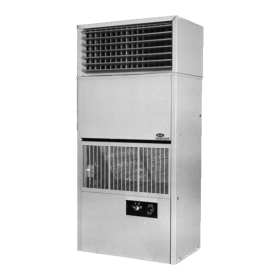
The 90MA/MU water cooled single-package cooling units
are designed to provide air conditioning aboard marine
vessels. The 90MA units are fitted with a water cooled
condenser and are factory charged, wired and piped. The
90MU units are similar to the 90MA except they are
configured for use of a remote mounted condenser.
An accessory discharge plenum may be installed to
provide free-blow into the conditioned space. Also, an
optional electric heater may be specified to provide comfort
heating.
INSTALLATION
Step 1 - Inspect Unit - Check unit against shipping order.
Inspect carefully for concealed shipping damage. If shipment
is damaged or incomplete, file claim with transportation
company and advise Carrier Transicold immediately.
Manufacturer reserves the right to discontinue, or change at any time, specifications or designs without notice and without incurring obligations
Printed in U.S.A.
Single-Package Marine Cooling Units
CONTENTS
SAFETY CONSIDERATIONS........................................1
GENERAL .....................................................................1
INSTALLATION.............................................................1
Step 1- Inspect Unit .......................................................1
Step 2 - Protect Unit from Damage ................................1
Step 3 - Provide Unit Support ........................................1
Step 4 - Rig and Place Unit............................................8
Step 5 - Install Accessory Plenum (If Supplied) ............8
Step 6 - Check Fan Shaft and Wheel Alignment ...........9
Step 8 - Check Return-Air Filters ...................................9
(*08 & *12) ................................................................9
Step 10 - Make Condenser Connections .......................9
Step 11 - Install Unit Drain Line ................................... 11
Step 12 - Make Electrical Connections ........................ 12
OPERATION................................................................ 12
To Start Unit................................................................. 12
To Shut Down Unit ....................................................... 12
Service Valves ............................................................. 12
SERVICE ..................................................................... 13
Return-Air Grill Removal .............................................. 13
Access Panel Removal ................................................ 13
Evaporator Fan Adjustment ......................................... 13
Lubrication ................................................................... 13
Return-Air Filters.......................................................... 13
Condensate Drains ...................................................... 13
Evaporator Coil ............................................................ 14
Water Regulating Valve ............................................... 14
Condenser ................................................................... 14
Charging the System.................................................... 15
Evaporator Fan Motor Removal ................................... 15
Pressure Relief Device................................................. 15
Crankcase Heater ........................................................ 15
Discharge And Suction Pressure Switches .................. 16
Oil Charge.................................................................... 16
WIRING SCHEMATIC - *04/*06................................... 17
COMPONENT ARRANGEMENT - *04/*06.................. 18
WIRING SCHEMATIC - *08/*12................................... 19
COMPONENT ARRANGEMENT - *08/*12.................. 20
UNIT SUPPORT DRAWINGS ..................................... 21
Step 2 - Protect Unit from Damage - To maintain warranty,
protect unit against adverse weather, theft, or vandalism on
job site.
Step 3 - Provide Unit Support - Refer to Figure 2 and
Tables 1A/B/C/2A/B/C for unit size and weight. If desired,
construct a frame of I-beams or angle iron that adequately
supports unit. See unit support drawings contained in this
document.
90MA-3SI
Pg 1
TM
Protection Device ................................... 15
SUPERCEDES FORM 62-02971-00 09-2009
90MA/MU
Page
Advertisement
Table of Contents

Related Manuals for Carrier 90MA


Summary of Contents for Carrier 90MA
-
Page 1: Table Of Contents
The 90MA/MU water cooled single-package cooling units are designed to provide air conditioning aboard marine vessels. The 90MA units are fitted with a water cooled condenser and are factory charged, wired and piped. The 90MU units are similar to the 90MA except they are configured for use of a remote mounted condenser. - Page 2 TABLE 1A - 90MA/MU PHYSICAL DATA – R-134A , ENGLISH UNITS (See Table 2A for SI units) BASE UNIT (90MA/MU) NOMINAL CAPACITY REFRIGERANT OPERATING WEIGHT Base unit 90MA Base Unit 90MU Discharge Plenum COMPRESSOR TYPE Qty Cylinders Qty Unloading Cylinders...
- Page 3 TABLE 1B - 90MA/MU PHYSICAL DATA – R-407C , ENGLISH UNITS (See Table 2B for SI units) BASE UNIT (90MA/MU) NOMINAL CAPACITY REFRIGERANT OPERATING WEIGHT Base unit 90MA Base Unit 90MU Discharge Plenum COMPRESSOR TYPE Qty Cylinders Qty Unloading Cylinders...
- Page 4 TABLE 1C - 90MA/MU PHYSICAL DATA – R-404A , ENGLISH UNITS (See Table 2C for SI units) BASE UNIT (90MA/MU) NOMINAL CAPACITY REFRIGERANT OPERATING WEIGHT Base unit 90MA Base Unit 90MU Discharge Plenum COMPRESSOR TYPE Qty Cylinders Qty Unloading Cylinders...
- Page 5 MPT = Male Pipe Thread NOTES: 1. Motors other than those furnished with unit must be purchased separately. Contact your Carrier Marine representative Manufacturer reserves the right to discontinue, or change at any time, specifications or designs without notice and without incurring obligations Printed in U.S.A.
- Page 6 MPT = Male Pipe Thread NOTES: 1. Motors other than those furnished with unit must be purchased separately. Contact your Carrier Marine representative Manufacturer reserves the right to discontinue, or change at any time, specifications or designs without notice and without incurring obligations Printed in U.S.A.
- Page 7 MPT = Male Pipe Thread NOTES: 1. Motors other than those furnished with unit must be purchased separately. Contact your Carrier Marine representative Manufacturer reserves the right to discontinue, or change at any time, specifications or designs without notice and without incurring obligations Printed in U.S.A.
-
Page 8: Step 4 - Rig And Place Unit
1. Certified dimension drawings available upon request 2. Minimum required clearance at back of unit is zero. Clearance above and at right (90MA*08,*12 only) and at left of unit depends on space required for accessory plenum, ductwork, condenser piping, accessory heater piping, condensate drain line and power wiring 3. -
Page 9: Step 6 - Check Fan Shaft And Wheel Alignment
Step 10 - Make Condenser Connections UNIT MOUNTED 90MA UNITS- Piping arrangements for condenser cooling water are shown in Figure. 5. Condensers have water inlet and outlet connections as shown in Figure 6. - Page 10 Recommended line sizes are given in Table 3. Additional instructions can be found in Carrier System Design Manual, Part 3, for standard refrigeration piping techniques. On *08 and *12 size units, secure discharge...
-
Page 11: Step 11 - Install Unit Drain Line
Manufacturer reserves the right to discontinue, or change at any time, specifications or designs without notice and without incurring obligations Printed in U.S.A. LENGTH OF RUN 0-25 26-50 LIQUID DISCH LIQUID 1-1/8 FIGURE 7 - CONDENSATE DRAIN TRAP 90MA-3SI Pg 11 51-75 76-100 DISCH LIQUID DISCH LIQUID 1-1/8 1-1/8... -
Page 12: Step 12 - Make Electrical Connections
Correct improper voltage or phase imbalance. Unit failure as a result of operation on improper line voltage or excessive phase imbalance constitutes abuse and shall void the Carrier warranty. Use the following formula to determine the percent voltage imbalance. CONTROL WIRING - On extended voltage (208/230-v) units, the control transformer is factory wired for 208-v usage. -
Page 13: Service
Condensate Drains - Clean the drain line and unit drain pan at the start of each cooling season. Check flow by pouring water into drain. Be sure trap is filled as shown in Figure. 7 to maintain an air seal. 90MA-3SI Pg 13 SUPERCEDES FORM 62-02971-00 09-2009... -
Page 14: Evaporator Coil
2. Install a calibrated gauge at the liquid line service port. FOR 90MA: Operating liquid line range for R-407C units is 200 to 215 psig, operating range for R-404A units is 240 to 260 psig, operating range for R-134a units is 122 to 130 psig. -
Page 15: Charging The System
Charging the System (90MA) - These units are shipped with a full operating charge. If recharging is necessary (complete charge lost), weigh in amount of refrigerant indicated on unit nameplate and in Table 1. If unit has partial charge, it must be recharged by removing existing charge and recharging by weighing in the required amount of refrigerant. -
Page 16: Discharge And Suction Pressure Switches
24 hours. When additional oil or a complete charge is required, use only the following Carrier approved oil. R-407C, R-404A, and R-134a units Castrol - Icematic SW68 ICI - Emkarate RL68HP Manufacturer reserves the right to discontinue, or change at any time, specifications or designs without notice and without incurring obligations Printed in U.S.A. -
Page 17: Wiring Schematic - *04/*06
FOR NOTES AND LEGEND, SEE FIGURE 13 FIGURE 12 WIRING SCHEMATIC - 90MA/MU*04/*06 Manufacturer reserves the right to discontinue, or change at any time, specifications or designs without notice and without incurring obligations Printed in U.S.A. 90MA-3SI SUPERCEDES FORM 62-02971-00 09-2009... -
Page 18: Component Arrangement - *04/*06
FIGURE 13 COMPONENT ARRANGEMENT - 90MA/MU*04/*06 Manufacturer reserves the right to discontinue, or change at any time, specifications or designs without notice and without incurring obligations Printed in U.S.A. 90MA-3SI SUPERCEDES FORM 62-02971-00 09-2009 Pg 18... -
Page 19: Wiring Schematic - *08/*12
FOR NOTES AND LEGEND, SEE FIGURE 15 FIGURE 14 - ELECTRICAL SCHEMATIC - 90MA/MU*08/*12 Manufacturer reserves the right to discontinue, or change at any time, specifications or designs without notice and without incurring obligations Printed in U.S.A. 90MA-3SI SUPERCEDES FORM 62-02971-00 09-2009... -
Page 20: Component Arrangement - *08/*12
FIGURE 15 - COMPONENT ARRANGEMENT - 90MA/MU008/012 Manufacturer reserves the right to discontinue, or change at any time, specifications or designs without notice and without incurring obligations Printed in U.S.A. 90MA-3SI SUPERCEDES FORM 62-02971-00 09-2009 Pg 20... -
Page 21: Unit Support Drawings
FIGURE 16 – MOUNTING BASE ASSEMBLY – 90MA/MU*04/*06 Manufacturer reserves the right to discontinue, or change at any time, specifications or designs without notice and without incurring obligations Printed in U.S.A. 90MA-3SI SUPERCEDES FORM 62-02971-00 09-2009 Pg 21... - Page 22 FIGURE 17 – MOUNTING BASE ASSEMBLY – 90MA/MU*08/*12 Manufacturer reserves the right to discontinue, or change at any time, specifications or designs without notice and without incurring obligations Printed in U.S.A. 90MA-3SI SUPERCEDES FORM 62-02971-00 09-2009 Pg 22...