Table of Contents
Advertisement
Quick Links
CoastIPC
.com
866-412-6278
Neousys Technology Inc.
Nuvo-3000 Series
rd
Intel® 3
-Gen Core™ i7/i5/i3 Fanless Controller
Nuvo-3005E/3005P
Nuvo-3003E/3003P
Nuvo-3005TB/3003TB
User's Manual
Rev. A1.1
th
Published September 4
, 2013
Copyright © 2013 Neousys Technology Inc. All Right Reserved.
Page 1 of 101
Advertisement
Table of Contents

Related Manuals for Neousys Technology Nuvo-3000 Series


Summary of Contents for Neousys Technology Nuvo-3000 Series
- Page 1 CoastIPC .com 866-412-6278 Neousys Technology Inc. Nuvo-3000 Series Intel® 3 -Gen Core™ i7/i5/i3 Fanless Controller Nuvo-3005E/3005P Nuvo-3003E/3003P Nuvo-3005TB/3003TB User’s Manual Rev. A1.1 Published September 4 , 2013 Copyright © 2013 Neousys Technology Inc. All Right Reserved. Page 1 of 101...
-
Page 2: Table Of Contents
2.3.2 3-Pin Terminal Block for DC Input & Ignition Input........30 2.3.3 COM Ports (COM1 & COM2) ...............31 2.3.4 Gigabit Ethernet Ports ................33 2.3.5 Auxiliary I/O ..................34 2.4 Internal I/O Functions..................35 Copyright © 2013 Neousys Technology Inc. All Right Reserved. Page 2 of 101... - Page 3 3.8.1 Principle of Ignition Power Control............73 3.8.2 Operation Modes of Ignition Power Control..........75 Chapter 4 BIOS and Driver ...................77 4.1 BIOS Settings.....................77 4.1.1 COM1 & COM2 Operating Mode............77 Copyright © 2013 Neousys Technology Inc. All Right Reserved. Page 3 of 101...
- Page 4 Using WDT Function....................90 WDT Function Reference.................90 Using DIO Function ....................92 Wiring for DIO ....................92 DIO Channel Definition ..................93 DIO Function Reference ..................94 Using COS Function ..................97 DI COS Example....................99 Copyright © 2013 Neousys Technology Inc. All Right Reserved. Page 4 of 101...
-
Page 5: Declaimer
Company/product names mentioned herein are used for identification purposes only and are trademarks and/or registered trademarks of their respective companies. Copyright © 2013 Neousys Technology Inc. All Right Reserved. Page 5 of 101... -
Page 6: Chapter 1 Introduction
Nuvo-3000 Series User’s Manual Chapter 1 Introduction 1.1 Overview Discover a leaping of embedded controller design with Neousys Nuvo-3000 series! Nuvo-3000 incorporates the cutting-edge processor technology and Neousys’ innovative Cassette architecture to construct a truly reliable and versatile embedded controller. Its 3rd-Gen i7 Quad-core processor delivers tremendous boost of computing power as well as significant improvement of graphics performance. -
Page 7: Product Specification
With Core™ i5-3610ME: 48.83W (2.57A@19V) Consumption With Celeron™ 1020E: 42.75W (2.25A@19V) Remote Ctrl. & Status 1x 10-pin (2x5) wafer connector for remote on/off control and status LED output Output Mechanical Copyright © 2013 Neousys Technology Inc. All Right Reserved. Page 7 of 101... -
Page 8: Specification Of Nuvo-3005P
2x software-programmable RS-232/422/485 (COM1 & COM2) KB/MS 1x 6-pin mini-DIN connector for PS/2 keyboard/mouse Audio 1x mic-in and 1x speaker-out Storage Interface SATA HDD 1x Internal SATA port for 2.5” HDD/SSD installation Copyright © 2013 Neousys Technology Inc. All Right Reserved. Page 8 of 101... - Page 9 ** The CPU loading for high-temperature test is applied using Intel® Thermal Analysis Tool. For detail testing criteria, please contact Neousys Technology *** For sub-zero operating temperature, a wide temperature HDD drive or Solid State Disk (SSD) is required. Copyright © 2013 Neousys Technology Inc. All Right Reserved. Page 9 of 101...
-
Page 10: Specification Of Nuvo-3003E
Dimension 240 mm (W) x 225 mm (D) x 88 mm (H) Weight 4.4 Kg (including 2.5” HDD and DDR3 SODIMM) Mounting Wall-mounting (Standard) or DIN-Rail mounting (optional) Copyright © 2013 Neousys Technology Inc. All Right Reserved. Page 10 of... -
Page 11: Specification Of Nuvo-3003P
1x mic-in and 1x speaker-out Storage Interface SATA HDD 1x Internal SATA port for 2.5” HDD/SSD installation 1x SATA port in Cassette for 3.5” HDD installation CFast 1x CFast socket Expansion Bus Copyright © 2013 Neousys Technology Inc. All Right Reserved. Page 11 of... - Page 12 ** The CPU loading for high-temperature test is applied using Intel® Thermal Analysis Tool. For detail testing criteria, please contact Neousys Technology *** For sub-zero operating temperature, a wide temperature HDD drive or Solid State Disk (SSD) is required. Copyright © 2013 Neousys Technology Inc. All Right Reserved. Page 12 of...
-
Page 13: Specification Of Nuvo-3005Tb
Dimension 240 mm (W) x 225 mm (D) x 85.5 mm (H) Weight 4.2 Kg (including 2.5” HDD and DDR3 SODIMM) Mounting Wall-mounting (Standard) or DIN-Rail mounting (optional) Copyright © 2013 Neousys Technology Inc. All Right Reserved. Page 13 of... -
Page 14: Specification Of Nuvo-3003Tb
1x mic-in and 1x speaker-out Storage Interface SATA HDD 1x Internal SATA port for 2.5” HDD/SSD installation 1x Internal SATA port for 3.5” HDD installation CFast 1x CFast socket Expansion Bus Copyright © 2013 Neousys Technology Inc. All Right Reserved. Page 14 of... - Page 15 ** The CPU loading for high-temperature test is applied using Intel® Thermal Analysis Tool. For detail testing criteria, please contact Neousys Technology *** For sub-zero operating temperature, a wide temperature HDD drive or Solid State Disk (SSD) is required. Copyright © 2013 Neousys Technology Inc. All Right Reserved. Page 15 of...
-
Page 16: Specification Of Optional Isolated Dio
100 mA (sustained loading) (per channel) 250 mA (peak loading) Isolated Voltage 2500 Vrms Operation Mode Polling, Change-of-State Interrupt Output Type Power MOSFET + Analog Device iCoupler® Operation Mode Polling I/O Copyright © 2013 Neousys Technology Inc. All Right Reserved. Page 16 of... -
Page 17: Supported Cpu List
Intel® Celeron® Processor 1020E (2M Cache, 2.20 GHz) * Intel® Celeron® Processor 1000M (2M Cache, 1.80 GHz) The processors with * are listed in Intel® Embedded Roadmap and with a 7-year life cycle support (2013~2019). Copyright © 2013 Neousys Technology Inc. All Right Reserved. Page 17 of... -
Page 18: Chapter 2 Getting To Know Your Nuvo-3000
Getting to know your Nuvo-3000 2.1 Unpacking your Nuvo-3000 When you receive the package of Nuvo-3000 series, please check immediately if the package contains all the items listed in the following table. If any item is missing or damaged, please contact your local dealer or Neousys Technology Inc. for further assistance. - Page 19 Nuvo-3000 Series User’s Manual M4 screws for wall-mounting bracket Foot pad 3-pin pluggable terminal block HDD thermal pads for 2.5” HDD/SSD and 3.5” HDD (if HDD is not installed) Copyright © 2013 Neousys Technology Inc. All Right Reserved. Page 19 of...
-
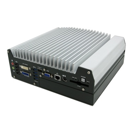
Page 20: Front Panel I/O Functions
Please note that a 5 seconds interval is kept by the system between two on/off operations (i.e. once turning off the system, you shall wait for 5 seconds to initiate another power-on operation). Copyright © 2013 Neousys Technology Inc. All Right Reserved. Page 20 of... -
Page 21: Reset Button
Watchdog timer indicator, flashing when watchdog timer is started. Use for auxiliary function. If ignition option is applied, this LED is AUX/IGN Green used to indicate ignition signal status. Copyright © 2013 Neousys Technology Inc. All Right Reserved. Page 21 of... -
Page 22: Cfast Socket
ITE8783 Super IO chip (-40 to 85°C). There is one 6-pin Mini-DIN connector on the front panel to provide PS/2 KB/MS signals. You shall need to use a Y-cable to connect PS/2 keyboard and mouse at the same time. Copyright © 2013 Neousys Technology Inc. All Right Reserved. Page 22 of... -
Page 23: Gigabit Ethernet Port
To utilize the GbE port in Windows, you need to install corresponding driver for Intel I210 ® GbE controller. Please refer to section 4.3.2 for information of driver installation. Copyright © 2013 Neousys Technology Inc. All Right Reserved. Page 23 of... -
Page 24: Vga Connector
LED indicators. Nuvo-3000 provides a 2x5, 2.0mm pitch wafer connector on the front panel for this purpose. Copyright © 2013 Neousys Technology Inc. All Right Reserved. Page 24 of... - Page 25 The status LED output has a built-in series-resistor and provides 3.3V, 10mA current, which means you can use these pins to directly drive an external LED indicator. Copyright © 2013 Neousys Technology Inc. All Right Reserved. Page 25 of...
-
Page 26: Usb 3.0 Connectors
Note Intel USB 3.0 driver does not support Windows XP. In Windows XP, all USB 3.0 ports will work in USB 2.0 mode. 2.2.10 DVI/HDMI Connectors Copyright © 2013 Neousys Technology Inc. All Right Reserved. Page 26 of... -
Page 27: Usb 2.0 Connectors
Control Interface) mode and are compatible with USB 2.0, USB 1.1 and USB 1.0 devices. Legacy USB support is provided so you can use USB keyboard/mouse in DOS environment. Copyright © 2013 Neousys Technology Inc. All Right Reserved. Page 27 of... -
Page 28: Speaker-Out And Mic-In Audio Jacks
Windows, you need to install corresponding drivers for both Intel HM76 ® PCH chipset and Realtek ALC262 codec. Please refer to section 4.3.2 for information of driver installation. Copyright © 2013 Neousys Technology Inc. All Right Reserved. Page 28 of... -
Page 29: Back Panel I/O Functions
You should use either 4-pin mini-DIN power connector or 3-pin pluggable terminal block for DC power input. DO NOT supply power to both connectors at the same time. Copyright © 2013 Neousys Technology Inc. All Right Reserved. Page 29 of... -
Page 30: 3-Pin Terminal Block For Dc Input & Ignition Input
You should use either 4-pin mini-DIN power connector or 3-pin pluggable terminal block for DC power input. DO NOT supply power to both connectors at the same time. Copyright © 2013 Neousys Technology Inc. All Right Reserved. Page 30 of... -
Page 31: Com Ports (Com1 & Com2)
For users who need the 3 COM port, Neousys offers a cable kit to connect the internal connector and expose a 9-pin D-Sub connector on the back panel. Copyright © 2013 Neousys Technology Inc. All Right Reserved. Page 31 of... - Page 32 Nuvo-3000 Series User’s Manual Pin# RS-232 Mode Copyright © 2013 Neousys Technology Inc. All Right Reserved. Page 32 of...
-
Page 33: Gigabit Ethernet Ports
To utilize the GbE port in Windows, you need to install corresponding driver for Intel I210 ® GbE controller. Please refer to section 4.3.2 for information of driver installation. Copyright © 2013 Neousys Technology Inc. All Right Reserved. Page 33 of... -
Page 34: Auxiliary I/O
Pin Definition Pin# Pin Definition ISO_5V DO_0 DO_GND DO_3 DO_1 DO_GND DO_2 DO_5 DO_4 DO_7 DO_6 DI_GND DO_GND DI_6 DI_GND DI_1 DI_5 DI_GND DI_3 DI_0 DI_7 DI_2 DI_GND DI_4 Copyright © 2013 Neousys Technology Inc. All Right Reserved. Page 34 of... -
Page 35: Internal I/O Functions
Nuvo-3000 provides two 204-pin, SODIMM sockets for installing DDR3 memory modules. It supports a maximal 16GB capacity by installing two 8GB DDR3 1600MHz SODIMM modules. For information of installing DDR3 memory modules, please refer to section 3.1 for detail. Copyright © 2013 Neousys Technology Inc. All Right Reserved. Page 35 of... -
Page 36: Internal Sata#1 Port
2.5” HDD/SSD. A special washer is installed to fix the SATA cable and make sure a very robust connection. For information of installing a HDD/SSD to SATA#1 port, please refer to section 3.2 for detail. Copyright © 2013 Neousys Technology Inc. All Right Reserved. Page 36 of... -
Page 37: Internal Sata#2 Port
SATA cable and make sure a very robust connection. For information of installing a HDD/SSD to SATA#2 port, please refer to section 3.3 for detail. One 2.5” HDD and one 3.5” HDD installed in Nuvo-300TB Copyright © 2013 Neousys Technology Inc. All Right Reserved. Page 37 of... -
Page 38: Mini Pci Express Connector#1 (With Sim Socket)
Internet in wide territory through telecom operator’s GPRS/3G network. For WIFI/3G communication, Nuvo-3000 provides multiple SMA antenna apertures on the front and back panel for multi-antenna configuration. Copyright © 2013 Neousys Technology Inc. All Right Reserved. Page 38 of... -
Page 39: Mini Pci Express Connector#2
PCI-E module. You can install versatile modules, such as WIFI, GPS, RAID controller, mini PCI-E DOM and etc. For communication modules which need external antenna connection, Nuvo-3000 provides multiple SMA antenna apertures on the front and back panel for multi-antenna configuration. Copyright © 2013 Neousys Technology Inc. All Right Reserved. Page 39 of... -
Page 40: Internal Usb 2.0 Ports
USB_4_N USB4 Differential data output - negative USB_5_N USB5 Differential data output - negative USB_4_P USB4 Differential data output - positive USB_5_P USB5 Differential data output - positive Copyright © 2013 Neousys Technology Inc. All Right Reserved. Page 40 of... -
Page 41: Internal Com Port (Com3)
COM3 supports RS-232 mode only. For users who need to connect devices via standard DSub-9 connectors, please refer to the following pin definition for wiring. Neousys also provides an optional cable kit to expose the DSub-9 connector. Copyright © 2013 Neousys Technology Inc. All Right Reserved. Page 41 of... -
Page 42: Rotary Switch For Ignition Power Control Mode
Nuvo-3000 Series User’s Manual Pin# RS-232 Mode 2.4.8 Rotary Switch for Ignition Power Control Mode Copyright © 2013 Neousys Technology Inc. All Right Reserved. Page 42 of... - Page 43 Nuvo-3000 Series User’s Manual Nuvo-3000 series offers the option of ignition power control module for in-vehicle applications. For Nuvo-3000 equipped with this option, the on-board rotary switch is used to configure the operation mode of ignition power control. Please refer to section 3.8 for information of using ignition power control.
-
Page 44: Expansion Cassette
Nuvo-3000 Series User’s Manual 2.5 Expansion Cassette The expansion Cassette is an innovation design on Nuvo-3000 series. By providing a separated chassis to accommodate add-on card, it’s more effective to manage the thermal conditions of both the system and the add-on card. The modular concept of Cassette also reduces the complexity of installing an add-on card into the fanless controller. -
Page 45: Cassette Of Nuvo-3000E
12VDC Fan Power (2A rated Current) SATA Signal Standard 7-pin SATA connector 4-pin, 2.0mm pitch wafer connector for supplying 5/12VDC Description 5/12VDC Power (2A rated Current) (2A rated Current) Copyright © 2013 Neousys Technology Inc. All Right Reserved. Page 45 of... -
Page 46: Cassette Of Nuvo-3000P
12VDC Fan Power (2A rated Current) SATA Signal Standard 7-pin SATA connector 4-pin, 2.0mm pitch wafer connector for supplying 5/12VDC Description 5/12VDC Power (2A rated Current) (2A rated Current) Copyright © 2013 Neousys Technology Inc. All Right Reserved. Page 46 of... -
Page 47: Fan Option Of Cassette
Cassette. If conduction-cooling scheme is needed, a customized a heat-spreader shall be made accordingly to contact components on add-on card and the surface of Cassette. Copyright © 2013 Neousys Technology Inc. All Right Reserved. Page 47 of... -
Page 48: Mechanical Dimension
Nuvo-3000 Series User’s Manual 2.6 Mechanical Dimension 2.6.1 Top View of Nuvo-3000E/3000P Copyright © 2013 Neousys Technology Inc. All Right Reserved. Page 48 of... -
Page 49: Front View Of Nuvo-3000E/3000P
Nuvo-3000 Series User’s Manual 2.6.2 Front View of Nuvo-3000E/3000P 2.6.3 Side View of Nuvo-3000E/3000P Copyright © 2013 Neousys Technology Inc. All Right Reserved. Page 49 of... -
Page 50: Bottom View Of Nuvo-3000E/3000P
Nuvo-3000 Series User’s Manual 2.6.4 Bottom View of Nuvo-3000E/3000P Copyright © 2013 Neousys Technology Inc. All Right Reserved. Page 50 of... -
Page 51: Top View Of Nuvo-3000Tb
Nuvo-3000 Series User’s Manual 2.6.5 Top View of Nuvo-3000TB Copyright © 2013 Neousys Technology Inc. All Right Reserved. Page 51 of... -
Page 52: Front View Of Nuvo-3000Tb
Nuvo-3000 Series User’s Manual 2.6.6 Front View of Nuvo-3000TB 2.6.7 Side View of Nuvo-3000TB Copyright © 2013 Neousys Technology Inc. All Right Reserved. Page 52 of... -
Page 53: Bottom View Of Nuvo-3000Tb
Nuvo-3000 Series User’s Manual 2.6.8 Bottom View of Nuvo-3000TB Copyright © 2013 Neousys Technology Inc. All Right Reserved. Page 53 of... -
Page 54: Chapter 3 Getting Start
Use a Philips screwdriver to loosen the M3 flat-head screw and open the “Pet-Door”. Use a Philips screwdriver to loosen four M4 flat-head screws on the Cassette. Pull up the Cassette to remove it from the Nuvo-3000E/3000P. Copyright © 2013 Neousys Technology Inc. All Right Reserved. Page 54 of... - Page 55 SODIMM module. Repeat this step if you want to install the second DDR3 SODIMM module. Copyright © 2013 Neousys Technology Inc. All Right Reserved. Page 55 of...
-
Page 56: Install A 2.5" Hdd/Ssd
Use a Philips screwdriver to fix the HDD with M3 flat-head screws. Please note that the HDD must be placed in the right direction as below. (another 2 screws are on the opposite side) Copyright © 2013 Neousys Technology Inc. All Right Reserved. Page 56 of... - Page 57 Tilt the HDD assembly and insert the wedge of HDD bracket to the bottom cover. Once it’s firmly wedged, push it down and fix it using a M3 flat-head screw. Copyright © 2013 Neousys Technology Inc. All Right Reserved. Page 57 of...
-
Page 58: Install A 3.5" Hdd (Nuvo-3000Tb Only)
You can choose the proper one (or two) for your 3.5” HDD. Fix the HDD brackets to the 3.5” HDD using #6-32 screws and then insert the damping pads to the HDD brackets. Copyright © 2013 Neousys Technology Inc. All Right Reserved. Page 58 of... - Page 59 Check if the thermal pad(s) contact well with both HDD and bottom cover. Attach the SATA cable from SATA#2 port to the 3.5” HDD. Recover the bottom cover of Nuvo-3000TB and fix it with hex bolts. Copyright © 2013 Neousys Technology Inc. All Right Reserved. Page 59 of...
-
Page 60: Install An Add-On Card Into Cassette
Cassette, please refer to the information listed below. Remove Cassette from Nuvo-3000 by loosening four M4 screws. Open Cassette by pushing its cover toward arrow pointing direction. Copyright © 2013 Neousys Technology Inc. All Right Reserved. Page 60 of... - Page 61 Install a PCI/PCIe add-on card into the PCI/PCIe connector. Note that the tail of faceplate of the add-on card must be inserted into the mortise. Tighten the add-on card using a M3 screw. Copyright © 2013 Neousys Technology Inc. All Right Reserved. Page 61 of...
- Page 62 Nuvo-3000 Series User’s Manual Recover Cassette and assemble it to Nuvo-3000. Fix Cassette with four M4 screws. Copyright © 2013 Neousys Technology Inc. All Right Reserved. Page 62 of...
-
Page 63: Mount Your Nuvo-3000
Place Nuvo-3000 on a flat surface and fix it with screws. You can also take advantage of the keyhole-shaped holes of mounting brackets to suspend Nuvo-3000 on the Wall. Copyright © 2013 Neousys Technology Inc. All Right Reserved. Page 63 of... - Page 64 Nuvo-3000 with another four M4 screws. This option can be useful if you want to deploy Nuvo-3000 inside an equipment cabinet where DIN rail is available. Copyright © 2013 Neousys Technology Inc. All Right Reserved. Page 64 of...
- Page 65 Nuvo-3000 Series User’s Manual Copyright © 2013 Neousys Technology Inc. All Right Reserved. Page 65 of...
-
Page 66: Connect Dc Power To You Nuvo-3000
The 4-pin mini-DIN power connector provides a convenient way for power input especially in an indoor environment where AC/DC power adapter is usually applied. Neousys provides a 120W AC/DC adapter for Nuvo-3000 series. To connect DC power via 4-pin mini-DIN power connector, please follow the instructions below. -
Page 67: Connect Dc Power Via 3-Pin Pluggable Terminal Block
(+) to positive (+) and ground (GND) to ground (GND). Insert the wires to correct contacts of pluggable terminal block and tighten clamping screws using a Philips screwdriver. Copyright © 2013 Neousys Technology Inc. All Right Reserved. Page 67 of... -
Page 68: Power On Your Nuvo-3000
ATX-mode power on/off control. The external non-latched switch acts exactly the same as the power button on the front panel. To power on Nuvo-3000 using an external non-latched switch (ATX-mode), please follow the steps listed below. Copyright © 2013 Neousys Technology Inc. All Right Reserved. Page 68 of... -
Page 69: Power On Nuvo-3000 Using Wake-On-Lan Function
Wake-on-LAN (WOL) is a mechanism to wake up a computer system from a S5 (system off with standby power) state via issuing a magic packet. Nuvo-3000 implements the Wake-on-LAN function for its first GbE port. Copyright © 2013 Neousys Technology Inc. All Right Reserved. Page 69 of... - Page 70 In Windows XP system, identify the Local Area Connection of corresponding Intel® I210 Gigabit Controller and click the Configure button. Click the Advanced tag, and configure the following two options accordingly. Copyright © 2013 Neousys Technology Inc. All Right Reserved. Page 70 of...
- Page 71 4.1.4 for the instruction of configuring this BIOS option. In Windows 7 system, identify the Local Area Connection of corresponding Intel® I210 Gigabit Controller and click the Configure button. Copyright © 2013 Neousys Technology Inc. All Right Reserved. Page 71 of...
- Page 72 Nuvo-3000 Series User’s Manual Click the Power Management tag, and check the following two options accordingly Copyright © 2013 Neousys Technology Inc. All Right Reserved. Page 72 of...
-
Page 73: Ignition Power Control
Nuvo-3000 Series User’s Manual 3.8 Ignition Power Control Nuvo-3000 series offers the option of ignition power control module for in-vehicle applications. It’s a MCU-based implementation that monitors the ignition signal and reacts to turn on/off the system according to predefined on/off delay. Its built-in algorithm supports further features such as ultra-low standby power, battery-low protection, system hard-off and etc. - Page 74 If the system is shutdown (by the application software) in prior to power-off delay expired, it will cut off the system power immediately to prevent further consumption of battery power. Copyright © 2013 Neousys Technology Inc. All Right Reserved. Page 74 of...
-
Page 75: Operation Modes Of Ignition Power Control
If Mode 1 is specified, the system automatically turns on the system when DC power is applied. A retry mechanism is designed to repeat the power-on cycle if the system is failed to boot up. Mode Power-on Delay Power-off Delay Hard-off Timeout Copyright © 2013 Neousys Technology Inc. All Right Reserved. Page 75 of... - Page 76 Mode Power-on Delay Power-off Delay Hard-off Timeout 30 seconds 2 hours 10 minutes 30 seconds 5 hours 10 minutes Copyright © 2013 Neousys Technology Inc. All Right Reserved. Page 76 of...
-
Page 77: Chapter 4 Bios And Driver
Set the [Set COM1 as] to a proper mode for COM1 of your Nuvo-3000. Set the [Set COM2 as] to a proper mode for COM2 of your Nuvo-3000. Copyright © 2013 Neousys Technology Inc. All Right Reserved. Page 77 of... -
Page 78: Sata Controller Mode
When Nuvo-3000 boots up, press F2 to enter BIOS setup utility. Go to [Advanced] [SATA Configuration]. Set the [HDC Configure as] to a proper mode for your Nuvo-3000. Copyright © 2013 Neousys Technology Inc. All Right Reserved. Page 78 of... -
Page 79: Power On After Power Failure Option
BIOS settings. Please refer to section 3.7.3 for instructions of using WOL function. To enable/disable “Wake on LAN” option: When Nuvo-3000 boots up, press F2 to enter BIOS setup utility. Go to [Power]. Copyright © 2013 Neousys Technology Inc. All Right Reserved. Page 79 of... -
Page 80: Watchdog Timer For Booting
Disable or select timeout value for [WDT for Booting] option. Once you give a timeout value, the [WDT Stop Option] option appears. You can select “Automatically after POST” or “Manually after Entering OS”. Copyright © 2013 Neousys Technology Inc. All Right Reserved. Page 80 of... -
Page 81: Select A Boot Device
Boot Manager and then select one of the devices, or select the boot device in BIOS settings. To select a boot device in BIOS: When Nuvo-3000 boots up, press F2 to enter BIOS setup utility. Go to [Boot] [Boot Device]. Copyright © 2013 Neousys Technology Inc. All Right Reserved. Page 81 of... - Page 82 Nuvo-3000 according to device (Advanced mode) or device category (Normal mode). You can use F5/F6 or +/- to change the boot order of devices or device categories. Copyright © 2013 Neousys Technology Inc. All Right Reserved. Page 82 of...
-
Page 83: Operating System Support
You can visit Intel website for further information. Neousys will keep this list updated as we continuously test other operating systems with Nuvo-3000. Please contact us for the latest OS support list. Copyright © 2013 Neousys Technology Inc. All Right Reserved. Page 83 of... -
Page 84: Driver Installation
Nuvo-3000 Series User’s Manual 4.3 Driver Installation Neousys Technology Inc. provides a very convenient utility in “Drivers & Utilities DVD” to allow the “One-Click” driver installation. This utility automatically detects your Windows operating system and installs all necessary drivers to your Nuvo-3000 with just one mouse click. -
Page 85: Install Drivers Manually
The recommended driver installation sequence is Chipset driver (x:\Driver_Pool\Chipset_7_Series\ALL\infinst_autol.exe) Graphics driver (x:\Driver_Pool\Graphics_3rd_i7\Win7_32\Setup.exe) Audio driver (x:\Driver_Pool\Audio_ALC262\Win7_ALL\Setup.exe) LAN driver (x:\Driver_Pool\GbE_I210\Win7_32\APPS\PROSETDX\Win32\DxSetup.exe) USB 3.0 driver (x:\\Driver_Pool\USB3_7_Series\Win7_ALL\Setup.exe) ME driver (x:\Driver_Pool\ME_7_Series\ALL\Setup.exe) Windows 7 64-bit Copyright © 2013 Neousys Technology Inc. All Right Reserved. Page 85 of... - Page 86 Nuvo-3000 Series User’s Manual The recommended driver installation sequence is Chipset driver (x:\Driver_Pool\Chipset_7_Series\ALL\infinst_autol.exe) Graphics driver (x:\Driver_Pool\Graphics_3rd_i7\Win7_64\Setup.exe) Audio driver (x:\Driver_Pool\Audio_ALC262\Win7_ALL\Setup.exe) LAN driver (x:\Driver_Pool\GbE_I210\Win7_64\APPS\PROSETDX\Winx64\DxSetup.exe) USB 3.0 driver (x:\\Driver_Pool\USB3_7_Series\Win7_ALL\Setup.exe) ME driver (x:\Driver_Pool\ME_7_Series\ALL\Setup.exe) Copyright © 2013 Neousys Technology Inc. All Right Reserved. Page 86 of...
-
Page 87: Appendix A Using Watchdog Timer & Isolated Dio
Appendix A Using Watchdog Timer & Isolated DIO Neousys Nuvo-3000 series provide a watchdog (WDT) timer function to ensure a more reliable system operation. The WDT is a hardware mechanism to reset the system if the watchdog timer is expired. Users can start the WDT and keeping resetting the timer to make sure the system or program is running. -
Page 88: Install Wdt And Dio Library
WDT and DIO library. Execute WDT_DIO_Setup.exe. The following dialog appears. Click “Next >” and specify the directory of installing related files. The default directory is C:\Neousys\WDT_DIO. Copyright © 2013 Neousys Technology Inc. All Right Reserved. Page 88 of... - Page 89 The WDT & DIO library will take effect after system rebooting. When you programming your WDT or DIO program, the related files are located in Header file: \Include Lib file: \Lib Function Reference: \Manual Sample Code: \Sample Copyright © 2013 Neousys Technology Inc. All Right Reserved. Page 89 of...
-
Page 90: Using Wdt Function
If value of unit is correct (0 or 1), this function returns TRUE, otherwise FALSE. Usage WORD tick=255; BYTE unit=1; //unit is second. BOOL bRet = SetWDT(tick, unit); //timeout value is 255 seconds Copyright © 2013 Neousys Technology Inc. All Right Reserved. Page 90 of... - Page 91 = ResetWDT() StopWDT Description Stop the countdown of WDT. When WDT is stopped, the WDT LED indicator stops blinking. Parameter None Return Value Always returns TRUE; Usage Copyright © 2013 Neousys Technology Inc. All Right Reserved. Page 91 of...
-
Page 92: Using Dio Function
0 (circuit disconnected from GND return). When logic 1 is specified, MOSFET is activated and GND return path is established. The digital output function on Nuvo-3000 series supports sinking current connection. The following diagrams are the suggested wiring for DO: Copyright ©... -
Page 93: Dio Channel Definition
Pin Definition Pin# Pin Definition ISO_5V DO_0 DO_GND DO_3 DO_1 DO_GND DO_2 DO_5 DO_4 DO_7 DO_6 DI_GND DO_GND DI_6 DI_GND DI_1 DI_5 DI_GND DI_3 DI_0 DI_7 DI_2 DI_GND DI_4 Copyright © 2013 Neousys Technology Inc. All Right Reserved. Page 93 of... -
Page 94: Dio Function Reference
The status (TRUE or FALSE) of the specified DI channel. Usage BYTE ch=3; //DI channel #3 BOOL DIChValue = DIReadLine(ch); //read DI channel #3 DIReadPort Description Read the entire isolated digital input port (8 channels). Parameter None Copyright © 2013 Neousys Technology Inc. All Right Reserved. Page 94 of... - Page 95 WORD value specifies the status of the DO port. For Nuvo-1000/1300af, value should be a value of 0~255. For Nuvo-2000, value should be a value of 0~4095. Return Value None Copyright © 2013 Neousys Technology Inc. All Right Reserved. Page 95 of...
- Page 96 Nuvo-3000 Series User’s Manual Usage WORD DOPortValue=0XFF; //11111111b DOWritePort(DOPortValue); //write DO port as 11111111b Copyright © 2013 Neousys Technology Inc. All Right Reserved. Page 96 of...
-
Page 97: Using Cos Function
Returns TRUE if setup successes, FALSE if setup failed. Usage COS_INT_SETUP setup; memset(&setup, 0, sizeof(setup)); setup.portMask = 0xff; // enable ch.0~7 setup.edgeMode = 0; // level setup.edgeType = 0x00; // Lo/Hi BOOL bRet = SetupDICOS(&setup, sizeof(setup)); Copyright © 2013 Neousys Technology Inc. All Right Reserved. Page 97 of... - Page 98 Syntax BOOL StartDICOS(void); Description Start DI Change-of-State interrupt Parameter None Return Value Returns TRUE if start procedure successes, FALSE if start procedure failed. Usage BOOL bRet = StartDICOS(); Copyright © 2013 Neousys Technology Inc. All Right Reserved. Page 98 of...
-
Page 99: Di Cos Example
//Step 1, initialize DIO library by invoking InitDIO() if ( ! InitDIO() ) printf("InitDIO --> FAILED\n"); return -1; printf("InitDIO --> PASSED\n"); Copyright © 2013 Neousys Technology Inc. All Right Reserved. Page 99 of... - Page 100 -4; printf("StartDICOS --> PASSED\n"); printf("\npress any key to stop...\n"); system("pause >nul"); //Step 5, stop the DI Change-of-State Interrupt operation if ( ! StopDICOS() ) printf("StopDICOS --> FAILED\n"); Copyright © 2013 Neousys Technology Inc. All Right Reserved. Page 100 of...
- Page 101 Nuvo-3000 Series User’s Manual return -5; printf("StopDICOS --> PASSED\n"); printf("\npress any key to exit...\n"); system("pause >nul"); return 0; Copyright © 2013 Neousys Technology Inc. All Right Reserved. Page 101 of...
Need help?
Do you have a question about the Nuvo-3000 Series and is the answer not in the manual?
Questions and answers