Table of Contents
Advertisement
Quick Links
Advertisement
Table of Contents

Subscribe to Our Youtube Channel
Related Manuals for Neousys Technology Nuvo-3100 Series


Summary of Contents for Neousys Technology Nuvo-3100 Series
- Page 1 Nuvo-3100 Series User’s Manual Neousys Technology Inc. Nuvo-3100 Series Intel® 3rd-Gen Core™ i7/i5 Fanless in-Vehicle Controller Nuvo-3100VTC Nuvo-3120 User’s Manual Rev. A1.3 Published Jan 27 , 2015 Copyright © 2014 Neousys Technology Inc. All Right Reserved. Page 1 of 99...
- Page 2 Nuvo-3120 is optional (page 10). - Remove E-mark from Nuvo-3120 certificate list (page 11). 2014/09/24 - Change Nuvo-3100VTC bracket to damping A1.2 version (page 53) 2015/01/27 Correct spell: protective film A1.3 Copyright © 2014 Neousys Technology Inc. All Right Reserved. Page 2 of 99...
-
Page 3: Table Of Contents
2.4.3 SATA Port for HDD Tray (Nuvo-3100VTC Only) ........28 2.4.4 Full-Size Mini-PCIe Connector (with SIM Socket) ........29 2.4.5 Full-Size mSATA Connector (with SIM Socket) ........30 Copyright © 2014 Neousys Technology Inc. All Right Reserved. Page 3 of 99... - Page 4 3.4.1 Mount your Nuvo-3100VTC with Dedicated Damping Brackets ....54 3.4.2 Mount your Nuvo-3120 on the Wall/Surface ........... 55 3.4.3 Mount your Nuvo-3100 Series on the DIN Rail ........57 3.5 Connect DC power to you Nuvo-3100 Series ............58 3.6 Power on your Nuvo-3100 Series .................
- Page 5 DOWriteLineChecked ....................94 DOWritePortChecked ....................94 Using COS Function ..................95 SetupDICOS ........................95 RegisterCallbackDICOS ....................96 StartDICOS ........................96 StopDICOS ........................97 DI COS Example ....................98 Copyright © 2014 Neousys Technology Inc. All Right Reserved. Page 5 of 99...
-
Page 6: Declaimer
This manual is intended to be used as a practical and informative guide only and is subject to change without prior notice. It does not represent commitment from Neousys Technology Inc. Neousys shall not be liable for direct, indirect, special, incidental, or consequential damages arising out of the use of the product or documentation, nor for any infringements upon the rights of third parties, which may result from such use. -
Page 7: Chapter 1 Introduction
Introducing the most compact in-vehicle fanless controller supporting PGA-type 3rd-Gen i7/i5 processor! Neousys’ Nuvo-3100 series features the dimension of only 212 mm x 165 mm x 62 mm. While other compact fanless controllers adopt low-voltage, BGA-type i7 CPU (17W TDP), Nuvo-3100 supports standard voltage, PGA-type i7/i5/i3 CPU for flexible CPU installation. -
Page 8: Product Specification
Ignition Control Ignition power control with user-selectable on/off delay With Core™ i7-3610QE: 68.8W (3.62A@19V)* Max. Power With Core™ i5-3610ME: 46.9W (2.47A@19V)* Consumption With Celeron™ 1020E: 41.4W (2.18A@19V)* Copyright © 2014 Neousys Technology Inc. All Right Reserved. Page 8 of 99... -
Page 9: Specification Of Nuvo-3120
* The maximal power consumption is measured in Max. Performance Mode with 100% CPU loading applied using Passmark® BurnInTest™ v7.0. For detail testing criteria, please contact Neousys Technology ** For sub-zero operating temperature, a wide temperature HDD drive or Solid State Disk (SSD) is required. - Page 10 10%~90% , non-condensing Vibration Operating, 5 Grms, 5-500 Hz, 3 Axes (w/ SSD, according to IEC60068-2-64) Shock Operating, 50 Grms, Half-sine 11 ms Duration (w/ SSD, according to Copyright © 2014 Neousys Technology Inc. All Right Reserved. Page 10 of 99...
-
Page 11: Specification Of Isolated Dio
* The maximal power consumption is measured in Max. Performance Mode with 100% CPU loading applied using Passmark® BurnInTest™ v7.0. For detail testing criteria, please contact Neousys Technology ** For sub-zero operating temperature, a wide temperature HDD drive or Solid State Disk (SSD) is required. -
Page 12: Supported Cpu List
Intel® Celeron® Processor 1020E (2M Cache, 2.20 GHz) * Intel® Celeron® Processor 1000M (2M Cache, 1.80 GHz) The processors with * are listed in Intel® Embedded Roadmap and with a 7-year life cycle support (2013~2019). Copyright © 2014 Neousys Technology Inc. All Right Reserved. Page 12 of 99... -
Page 13: Chapter 2 Getting To Know Your Nuvo-3100
Getting to know your Nuvo-3100 2.1 Unpacking your Nuvo-3100 Series When you receive the package of Nuvo-3100 series, please check immediately if the package contains all the items listed in the following table. If any item is missing or damaged, please contact your local dealer or Neousys Technology for further assistance. -
Page 14: Front Panel I/O Functions
Nuvo-3100 Series User’s Manual 2.2 Front Panel I/O Functions On Nuvo-3100 series, plenty of I/O functions are provides on front panel and back panel so you can easily access them. Most common computer I/O functions are placed on the front panel. -
Page 15: Led Indicators
WLAN/WWAN LED Indicator for full-size mini-PCIe slot with SIM Green WLAN/WWAN LED Indicator for full-size mSATA slot with SIM Right Green WLAN/WWAN LED Indicator for half-size mini-PCIe slot Copyright © 2014 Neousys Technology Inc. All Right Reserved. Page 15 of 99... -
Page 16: Usb 3.0 Connectors
Nuvo-3100 Series User’s Manual 2.2.5 USB 3.0 Connectors Nuvo-3100 series offers four USB 3.0 (SuperSpeed USB) ports on its front panel. By BIOS default, these USB ports are operated in xHCI (eXtensible Host Controller Interface) mode and are compatible with USB 3.0, USB 2.0, USB 1.1 and USB 1.0 devices. Legacy USB support is also provided so you can use USB keyboard/mouse in DOS environment. -
Page 17: Dvi/Hdmi Connectors
1080 resolution. The VGA output supports up to 2048x1536 resolution. For VGA monitor, Neousys offers a dedicated DVI-to-VGA adapter as an accessory shipped with Nuvo-3100 series. This adapter supports VGA DDC signals and thus eliminates compatibility issues with VGA monitors. Or you can use a DVI-I to VGA+DVI-D Y-cable to support two independent display outputs. -
Page 18: Com Ports (Com1 & Com2)
Nuvo-3100 Series User’s Manual 2.2.8 COM Ports (COM1 & COM2) Nuvo-3100 series provides two COM ports via two 9-pin D-Sub male connectors on the front panel for communicating with external devices. They are implemented using industrial-grade ITE8783 Super IO chip (-40 to 85°C) and provide up to 115200 bps baud rate. -
Page 19: Hot-Swappable Hdd Tray (Nuvo-3100Vtc Only)
OS installation or RAID 0/1 operation with the first HDD. You can configure the operation mode of this SATA port in BIOS. Please refer to section 4.1.2/4.1.3 for further information. Copyright © 2014 Neousys Technology Inc. All Right Reserved. Page 19 of 99... -
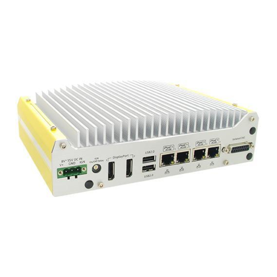
Page 20: Back Panel I/O Functions
2.3.1 3-Pin Terminal Block for DC Input & Ignition Input Nuvo-3100 series allows a wide range of DC power input from 8 to 35V via a 3-pin pluggable terminal block. It is fit for field usage where DC power is usually provided and its screw clamping connection of terminal block gives a very reliable way of wiring the DC power. -
Page 21: Ign On/Off Delay Configuration Switch (Nuvo-3100Vtc Only)
AT mode (power on after power supplied) Remote On/Off control mode (available for both Nuvo-3100VTC & Nuvo-3120) 10 seconds 10 seconds 10 minutes 10 seconds 1 minute 10 minutes Copyright © 2014 Neousys Technology Inc. All Right Reserved. Page 21 of 99... -
Page 22: Displayport Ports
5 hours 10 minutes 2.3.3 DisplayPort Ports Nuvo-3100 series supports triple independent display outputs via a DVI-I/HDMI connector (front panel) and two DisplayPort connectors (back panel). The DisplayPort connectors on the back panel support up to 2560 x 1600 resolution. -
Page 23: Usb 2.0 Connectors
Nuvo-3100 Series User’s Manual 2.3.4 USB 2.0 Connectors In addition to four USB 3.0 ports, Nuvo-3100 series provides another two USB 2.0 ports on the back panel. By BIOS default, these USB 2.0 ports are operated in EHCI (Enhanced Host Control Interface) mode and are compatible with USB 2.0, USB 1.1 and USB 1.0 devices. -
Page 24: Gigabit Ethernet Ports (Nuvo-3120)
Active/Link LED LED Color Status Description Yellow Ethernet port is disconnected Ethernet port is connected and no data transmission Flashing Ethernet port is connected and data is transmitting/receiving Copyright © 2014 Neousys Technology Inc. All Right Reserved. Page 24 of 99... -
Page 25: Isolated Dio
4.4 for information of driver installation for Windows XP/7/8. 2.3.7 Isolated DIO Nuvo-3100 series provides 4x isolated digital input channels and 4x isolated digital output channels. DIO function on Nuvo-3100 series supports polling mode I/O access and DI Change-of-State interrupt. -
Page 26: Internal I/O Functions
Nuvo-3100 Series User’s Manual 2.4 Internal I/O Functions In addition to I/O connectors on the front/back panel, Nuvo-3100 series provides other useful features via its on-board connectors, such as SATA ports, mini-PCIe sockets, internal USB ports, optional COM ports and etc. In this section, we’ll illustrate these internal I/O functions. -
Page 27: Sata Port For Internal Hdd/Ssd
Nuvo-3100 Series User’s Manual 2.4.2 SATA Port for Internal HDD/SSD Nuvo-3100 series provides internal SATA ports to accommodate SATA hard drives. Each SATA port is composed of a 7-pin SATA connector and a 4-pin power connector. SATA#1 Port is used in conjunction with the HDD bracket on “Pet-Door” to accommodate a 2.5”... -
Page 28: Sata Port For Hdd Tray (Nuvo-3100Vtc Only)
Nuvo-3100 Series User’s Manual 2.4.3 SATA Port for HDD Tray (Nuvo-3100VTC Only) Nuvo-3100 series provides internal SATA ports to accommodate SATA hard drives. Each SATA port is composed of a 7-pin SATA connector and a 4-pin power connector. SATA#2 Port is assembled and connected to the hot-swappable HDD tray of Nuvo-3100VTC. For information of accessing the hot-swappable HDD tray, please refer to section 3.2.2 for... -
Page 29: Full-Size Mini-Pcie Connector (With Sim Socket)
GPRS/3G network. A dedicated LED indicator on front panel presents the status of wireless communication for this full-size mini-PCIe socket. Nuvo-3100 series also provides multiple SMA antenna apertures on the back panel for antenna installation. Copyright © 2014 Neousys Technology Inc. All Right Reserved. -
Page 30: Full-Size Msata Connector (With Sim Socket)
GPRS/3G network. A dedicated LED indicator on front panel presents the status of wireless communication for this full-size mSATA socket. Nuvo-3100 series also provides multiple SMA antenna apertures on the back panel for antenna installation. Copyright © 2014 Neousys Technology Inc. All Right Reserved. -
Page 31: Half-Size Mini-Pcie Connector
A dedicated LED indicator on front panel presents the status of wireless communication for this half-size min-PCIe socket. Nuvo-3100 series also provides multiple SMA antenna apertures on the back panel for antenna installation. Copyright © 2014 Neousys Technology Inc. All Right Reserved. -
Page 32: Mechanical Dimension
Nuvo-3100 Series User’s Manual 2.5 Mechanical Dimension 2.5.1 Top View of Nuvo-3100VTC Copyright © 2014 Neousys Technology Inc. All Right Reserved. Page 32 of 99... -
Page 33: Front View Of Nuvo-3100Vtc
Nuvo-3100 Series User’s Manual 2.5.2 Front View of Nuvo-3100VTC 2.5.3 Side View of Nuvo-3100VTC Copyright © 2014 Neousys Technology Inc. All Right Reserved. Page 33 of 99... -
Page 34: Bottom View Of Nuvo-3100Vtc
Nuvo-3100 Series User’s Manual 2.5.4 Bottom View of Nuvo-3100VTC Copyright © 2014 Neousys Technology Inc. All Right Reserved. Page 34 of 99... -
Page 35: Top View Of Nuvo-3120
Nuvo-3100 Series User’s Manual 2.5.5 Top View of Nuvo-3120 Copyright © 2014 Neousys Technology Inc. All Right Reserved. Page 35 of 99... -
Page 36: Front View Of Nuvo-3120
Nuvo-3100 Series User’s Manual 2.5.6 Front View of Nuvo-3120 2.5.7 Side View of Nuvo-3120 Copyright © 2014 Neousys Technology Inc. All Right Reserved. Page 36 of 99... -
Page 37: Bottom View Of Nuvo-3120
Nuvo-3100 Series User’s Manual 2.5.8 Bottom View of Nuvo-3120 Copyright © 2014 Neousys Technology Inc. All Right Reserved. Page 37 of 99... -
Page 38: Chapter 3 Getting Start
Chapter 3 Getting Start 3.1 Install DDR3 SODIMM Modules Nuvo-3100 series provides one 204-pin, SODIMM socket for installing DDR3 memory module. It supports a maximal 8GB capacity by installing one 8GB DDR3 1600MHz SODIMM module. You can install/replace DDR3 SODIMM modules by following the steps listed below. -
Page 39: Install Ddr3 Sodimm Module To Nuvo-3120
Put the Nuvo-3120 upside down on a flat surface. You can see the “Pet-Door” exposed. Use a Philips screwdriver to loosen the M3 flat-head screw and open it. Copyright © 2014 Neousys Technology Inc. All Right Reserved. Page 39 of 99... - Page 40 Tilt the HDD assembly and insert the wedge of HDD bracket to the bottom cover. Once it’s firmly wedged, push it down and fix it using a M3 flat-head screw. Copyright © 2014 Neousys Technology Inc. All Right Reserved. Page 40 of 99...
-
Page 41: Install 2.5" Hdd/Ssd
Use a Philips screwdriver to fix the HDD with M3 flat-head screws. Please note that the HDD must be placed in the right direction as below. Copyright © 2014 Neousys Technology Inc. All Right Reserved. Page 41 of 99... - Page 42 Tilt the HDD assembly and insert the wedge of HDD bracket to the bottom cover. Once it’s firmly wedged, push it down and fix it using a M3 flat-head screw. Copyright © 2014 Neousys Technology Inc. All Right Reserved. Page 42 of 99...
-
Page 43: Install 2.5" Hdd To Hot-Swappable Hdd Tray Of Nuvo-3100Vtc
Insert the 2.5” HDD into the hot-swappable HDD tray, and please note the HDD direction when you install it. Push the handle back to the HDD tray along with the 2.5” HDD till it snaps into the latching position. Copyright © 2014 Neousys Technology Inc. All Right Reserved. Page 43 of 99... -
Page 44: Install 2.5" Hdd To Pet-Door Of Nuvo-3120
Use a Philips screwdriver to fix the HDD with M3 flat-head screws. Please note that the HDD must be placed in the right direction as below. Copyright © 2014 Neousys Technology Inc. All Right Reserved. Page 44 of 99... - Page 45 Tilt the HDD assembly and insert the wedge of HDD bracket to the bottom cover. Once it’s firmly wedged, push it down and fix it using a M3 flat-head screw. Copyright © 2014 Neousys Technology Inc. All Right Reserved. Page 45 of 99...
-
Page 46: Install Mini-Pcie Module
Turn your Nuvo-3100VTC to normal position. Unscrew 4 hex bolts on the top of the heat sink. Unscrew 5 hex bolts on the front panel and remove the front panel. Copyright © 2014 Neousys Technology Inc. All Right Reserved. Page 46 of 99... - Page 47 (full-size & half-size mini-PCIe socket) (mSATA socket) Tilt the mini-PCIe module and insert it into the mini-PCIe/mSATA socket. And fix the module with two M2.5 P-head screws. Copyright © 2014 Neousys Technology Inc. All Right Reserved. Page 47 of 99...
- Page 48 SATA signal and power cables for HDD tray reaches the connectors. Plug the SATA and power cable into connectors then push the bottom cover till it’s fully attached to back panel. Copyright © 2014 Neousys Technology Inc. All Right Reserved. Page 48 of 99...
- Page 49 12. Tilt the HDD assembly and insert the wedge of HDD bracket to the bottom cover. Once it’s firmly wedged, push it down and fix it using a M3 flat-head screw. 13. Attach the antenna to the SMA connector. Copyright © 2014 Neousys Technology Inc. All Right Reserved. Page 49 of 99...
-
Page 50: Install Mini-Pcie Module To Nuvo-3120
Turn your Nuvo-3120 to normal position. Unscrew 4 hex bolts on the top of the heat sink. Unscrew 5 hex bolts on the front panel and remove the front panel. Copyright © 2014 Neousys Technology Inc. All Right Reserved. Page 50 of 99... - Page 51 (full-size & half-size mini-PCIe socket) (mSATA socket) Tilt the mini-PCIe/mSATA module and insert it to the mini-PCIe/mSATA socket. And fix the module with two M2.5 P-head screws. Copyright © 2014 Neousys Technology Inc. All Right Reserved. Page 51 of 99...
- Page 52 11. Fix 2 hex bolts on the back-panel. 12. Assemble the front panel with Nuvo-3120 PCBA/heat-sink assembly and fix 5 hex bolts on it. Copyright © 2014 Neousys Technology Inc. All Right Reserved. Page 52 of 99...
- Page 53 13. Tilt the HDD assembly and insert the wedge of HDD bracket to the bottom cover. Once it’s firmly wedged, push it down and fix it using a M3 flat-head screw 14. Attach the antenna to the SMA connector. Copyright © 2014 Neousys Technology Inc. All Right Reserved. Page 53 of 99...
-
Page 54: Mount Your Nuvo-3100 Series
Nuvo-3100 Series User’s Manual 3.4 Mount your Nuvo-3100 Series Nuvo-3100 series provides versatile ways of mounting. Nuvo-3100VTC is shipped with dedicated damping brackets for in-vehicle installation. Or you can use wall-mounting brackets shipped with Nuvo-3120 to mount it on the wall/surface. Neousys also offers optional bracket and DIN rail clip to mount Nuvo-3100VTC/3120 on a DIN rail. -
Page 55: Mount Your Nuvo-3120 On The Wall/Surface
Nuvo-3120 on the wall/surface by following the steps listed below. Get two wall-mounting brackets and four M4 screws from the accessory box. Fix the mounting brackets to Nuvo-3120 using M4 screws. Copyright © 2014 Neousys Technology Inc. All Right Reserved. Page 55 of 99... - Page 56 Place Nuvo-3120 on a flat surface and fix it with screws. You can also take advantage of the keyhole-shaped holes of mounting brackets to suspend Nuvo-3120 on the Wall. For best efficiency of heat dissipation, please mount Nuvo-3120 in a right direction. Copyright © 2014 Neousys Technology Inc. All Right Reserved. Page 56 of 99...
-
Page 57: Mount Your Nuvo-3100 Series On The Din Rail
DIN-rail mounting clip. You should fix the clip to the bracket using four M4 flat-head screws first, and then fix the bracket assembly to Nuvo-3100 series with another four M4 screws. This option can be useful if you want to deploy Nuvo-3100 series inside an equipment cabinet where DIN rail is available. -
Page 58: Connect Dc Power To You Nuvo-3100 Series
Nuvo-3100 series accepts 8~35 VDC when using terminal block for DC input. Please make sure the voltage and polarity of DC power is correct before you connect it to Nuvo-3100 series. Supplying a voltage over 35V will damage the system. -
Page 59: Power On Your Nuvo-3100 Series
Power on Nuvo-3100 Series Using the Power Button This is the simplest way to turn on your Nuvo-3100 series. The power button on the front panel is a non-latched switch and behaves the ATX-mode on/off control. As DC power is connected, push the power button will turn on the system as well as the PWR LED indicator. -
Page 60: Power On Nuvo-3100 Series Using Wake-On-Lan Function
Wake-on-LAN (WOL) is a mechanism to wake up a computer system from a S5 (system off with standby power) state via issuing a magic packet. Nuvo-3100 series implements the Wake-on-LAN function for its first GbE port. To enable WOL function and power on you Nuvo-3100 series, please follow the steps listed below. For Windows XP When Nuvo-3100 series boots up, press F2 to enter BIOS setup utility. - Page 61 Click the Power Management tag, and configure the following two options accordingly. Wake on Magic Packet Nuvo-3100 series can wake from S5 state when receiving a magic packet. The magic packet is a broadcast frame containing anywhere within its payload 6 bytes of all 255 (FF FF FF FF FF FF in hexadecimal), followed by sixteen repetitions of the target computer's 48-bit MAC address.
- Page 62 When Nuvo-3100 boots up, press F2 to enter BIOS setup utility. Enter the [Power] menu. And configure the [Wake On LAN] option as [Enabled]. This setting enables the Wake-on-LAN function for Nuvo-3100 series. Please refer to section 4.1.8 for the instruction of configuring this BIOS option.
- Page 63 Nuvo-3100 Series User’s Manual Click the Power Management tag, and check the following two options accordingly Copyright © 2014 Neousys Technology Inc. All Right Reserved. Page 63 of 99...
-
Page 64: Ignition Power Control (Nuvo-3100Vtc Only)
11) As MCU detects system is off, it turns off the standby power for Nuvo-3100VTC, and then operates in low power mode again (< 2mW power consumption). Copyright © 2014 Neousys Technology Inc. All Right Reserved. Page 64 of 99... -
Page 65: Wiring Ignition Signal
To have ignition power control for in-vehicle usage, you need to supply IGN signal to Nuvo-3100VTC. The IGN input is located on the back panel via a 3-pin pluggable terminal Copyright © 2014 Neousys Technology Inc. All Right Reserved. Page 65 of 99... - Page 66 Please make sure your DC power source and IGN signal share the same ground. IGN input of Nuvo-3100VTC accepts 8~35VDC. Supply a voltage higher than 35VDC may damage the system. Copyright © 2014 Neousys Technology Inc. All Right Reserved. Page 66 of 99...
-
Page 67: Operation Modes Of Ignition Power Control
Each mode supports a hard-off timeout of 10 minutes. Mode Power-on Delay Power-off Delay Hard-off Timeout 10 seconds 10 seconds 10 minutes 30 seconds 1 minute 10 minutes Copyright © 2014 Neousys Technology Inc. All Right Reserved. Page 67 of 99... - Page 68 Mode 3 ~ Mode 12 Mode 2 ~ Mode 12 are ignition power control modes with various power-on delay and power-off delay. Each mode supports a hard-off timeout of 10 minutes. Copyright © 2014 Neousys Technology Inc. All Right Reserved. Page 68 of 99...
- Page 69 Mode Power-on Delay Power-off Delay Hard-off Timeout 30 seconds 2 hours 10 minutes 3 minutes 2 hours 10 minutes 30 seconds 5 hours 10 minutes Copyright © 2014 Neousys Technology Inc. All Right Reserved. Page 69 of 99...
-
Page 70: Chapter 4 Bios And Driver
Chapter 4 BIOS and Driver 4.1 BIOS Settings Nuvo-3100 series is shipped with factory-default BIOS settings cautiously programmed for best performance and compatibility. In this section, we’ll illustrate some of BIOS settings you may need to modify. Please always make sure you understand the effect of change before you proceed with any modification. -
Page 71: Sata Controller Mode For Nuvo-3100Vtc
When Nuvo-3100VTC boots up, press F2 to enter BIOS setup utility. Go to [Advanced] [IDE Configuration]. Set the [HDC Configure as] to a proper mode for your Nuvo-3100VTC. Copyright © 2014 Neousys Technology Inc. All Right Reserved. Page 71 of 99... -
Page 72: Configure Hot-Swappable Hdd Tray Of Nuvo-3100Vtc
If you need to configure the HDD tray as fixed storage device, please set the [SATA Port HotPlug] to [Disabled]. If you need to configure the HDD tray as removable storage device, please set the [SATA Port HotPlug] to [Enabled]. Copyright © 2014 Neousys Technology Inc. All Right Reserved. Page 72 of 99... -
Page 73: Sata Controller Mode For Nuvo-3120
When Nuvo-3120 boots up, press F2 to enter BIOS setup utility. Go to [Advanced] [IDE Configuration]. Set the [HDC Configure as] to a proper mode for your Nuvo-3100VTC. Copyright © 2014 Neousys Technology Inc. All Right Reserved. Page 73 of 99... -
Page 74: Power On After Power Failure Option
Nuvo-3100 Series User’s Manual 4.1.5 Power On after Power Failure Option This option defines the behavior of Nuvo-3100 series when DC power is supplied. Value Description S0 – Power On System is powered on when DC power is supplied. S5 – Power Off System is kept in off state when DC power is supplied. -
Page 75: W_Disable# For Mini-Pcie Sockets
Nuvo-3100 Series User’s Manual 4.1.6 W_DISABLE# for Mini-PCIe Sockets Nuvo-3100 series feature two mini-PCIe sockets and one mSATA socket for function expansion. According to PCI Express Mini Card Specification Rev. 2.0, two signals, W_DISABLE1# and W_DISABLE2#, are defined to enable/disable radio operation of add-on modules. -
Page 76: System Operating Mode
Nuvo-3100 Series User’s Manual 4.1.7 System Operating Mode Nuvo-3100 series supports PGA-type CPU to offer greater flexibility for CPU selection. PGA-type processors are with higher CPU power, and therefore introduce higher performance and more heat. For adapting to various environments, Nuvo-3100 series features a unique BIOS option, System Operating Mode, to alter CPU power per user’s... -
Page 77: Wake On Lan Option
Enable/disable the [Wake on LAN] option according to your application. 4.1.9 Watchdog Timer for Booting The BIOS of Nuvo-3100 series has a useful feature which allows users to use the watchdog timer to secure the booting process. You can specify the timeout value for watchdog timer. - Page 78 Disable or select timeout value for [WDT for Booting] option. Once you give a timeout value, the [WDT Stop Option] option appears. You can select “Automatically after POST” or “Manually after Entering OS”. Copyright © 2014 Neousys Technology Inc. All Right Reserved. Page 78 of 99...
-
Page 79: Select A Boot Device
Nuvo-3100 according to [By Device] or [By Device Type]. You can use F5/F6 or +/- to change the boot order of devices or device categories. Copyright © 2014 Neousys Technology Inc. All Right Reserved. Page 79 of 99... -
Page 80: Configure Amt (Nuvo-3100Vtc Only)
Select “MEBx Login” and you’re asked for password. The default password is “admin”. For further AMT configuration, please refer to Intel® MEBX User Guide for Intel® 7 Series Chipset. You can find related information at http://www.intel.com/support/motherboards/desktop/sb/CS-033768.htm Copyright © 2014 Neousys Technology Inc. All Right Reserved. Page 80 of 99... -
Page 81: Operating System Support
Nuvo-3100 Series User’s Manual 4.3 Operating System Support Nuvo-3100 series supports most operating system developed for Intel® x86 architecture. The following list contains the operating systems which have been tested in Neousys Technology Inc. Microsoft Window XP 32-bit Microsoft Window 7 32-bit... -
Page 82: Driver Installation
Neousys Technology Inc. provides a very convenient utility in “Drivers & Utilities DVD” to allow the “One-Click” driver installation. This utility automatically detects your Windows operating system and installs all necessary drivers to your Nuvo-3100 series with just one mouse click. -
Page 83: Install Drivers Manually
Nuvo-3100 Series User’s Manual 4.4.2 Install Drivers Manually You can also manually install each driver for Nuvo-3100 series. Please refer to the following information about installing drivers for different operating system. Windows XP SP3 The recommended driver installation sequence is Chipset driver (x:\Driver_Pool\Chipset_7_Series\XP\infinst_autol.exe) - Page 84 ME driver (x:\Driver_Pool\ME_7_Series\Win7_8_AMT\Setup.exe) Windows 8 64-bit The recommended driver installation sequence is Chipset driver (x:\Driver_Pool\Chipset_7_Series\Win7_8_ALL\SetupChipset.exe) Graphics driver (x:\Driver_Pool\Graphics_3rd_i7_Vlv\Win7_8_64\Setup.exe) Audio driver (x:\Driver_Pool\Audio_ALC262\Win7_8_ALL\Setup.exe) LAN driver (x:\Driver_Pool\GbE_I210\Win7_8_64\APPS\PROSETDX\Winx64\DxSetup.exe) ME driver (x:\Driver_Pool\ME_7_Series\Win7_8_AMT\Setup.exe) Copyright © 2014 Neousys Technology Inc. All Right Reserved. Page 84 of 99...
-
Page 85: Appendix A Using Watchdog Timer & Isolated Dio
Appendix A Using Watchdog Timer & Isolated DIO Nuvo-3100 series provide a watchdog (WDT) timer function to ensure a more reliable system operation. The WDT is a hardware mechanism to reset the system if the watchdog timer is expired. Users can start the WDT and keeping resetting the timer to make sure the system or program is running. -
Page 86: Install Wdt And Dio Library
WDT_DIO driver Rev. 2.06 or later to support WDT and DIO functions for Nuvo-3100 series. Execute WDT_DIO_Setup.exe. The following dialog appears. Click “Next >” and specify the directory of installing related files. The default directory is C:\Neousys\WDT_DIO. Copyright © 2014 Neousys Technology Inc. All Right Reserved. Page 86 of 99... - Page 87 Function Reference: \Manual Sample Code: \Sample\WDT_Demo (Watchdog Demo) \Sample\DIO_Demo (Polling I/O Demo) \Sample\COS_Demo (Change-of-State Interrupt Demo) \Sample\DTIO_Demo (DTIO Demo) \Sample\DTFO_Demo (Trigger Fan-out Demo) \Sample\PoE_Demo (PoE per-port Control Demo) Copyright © 2014 Neousys Technology Inc. All Right Reserved. Page 87 of 99...
-
Page 88: Using Wdt Function
If value of unit is correct (0 or 1), this function returns TRUE, otherwise FALSE. Usage WORD tick=255; BYTE unit=1; //unit is second. BOOL bRet = SetWDT(tick, unit); //timeout value is 255 seconds Copyright © 2014 Neousys Technology Inc. All Right Reserved. Page 88 of 99... -
Page 89: Startwdt
Stop the countdown of WDT. When WDT is stopped, the WDT LED indicator stops blinking. Parameter None Return Value Always returns TRUE; Usage BOOL bRet = StopWDT() Copyright © 2014 Neousys Technology Inc. All Right Reserved. Page 89 of 99... -
Page 90: Using Dio Function
Using DIO Function Wiring for DIO The digital input function of Nuvo-3100 series is implemented using a photo-coupler with a internally series-connected 2.4kΩ resistor. You need to provide a voltage to specify the logic high/low state. The input voltage for logic high is 5~24V, and the input voltage for logic low is 0~1.5V. -
Page 91: Dio Pin Definition
Nuvo-3100 Series User’s Manual DIO Pin Definition Pin# Pin Definition Pin# Pin Definition DI_0 DI_GND DI_1 DI_2 DI_GND DI_3 DO_GND DO_GND DO_0 DO_2 DO_1 DO_3 ISO_5V DO_GND Copyright © 2014 Neousys Technology Inc. All Right Reserved. Page 91 of 99... -
Page 92: Dio Function Reference
Read a single channel of isolated digital input. Parameter BYTE value specifies the DI channel to be read. For Nuvo-3100 series, ch should be a value of 0 ~ 3. Return Value The status (TRUE or FALSE) of the specified DI channel. -
Page 93: Dowriteline
Write a single channel of isolated digital output. Parameter BYTE value specifies the DO channel to be written. For Nuvo-3100 series, ch should be a value of 0 ~ 3. value BOOL value (TRUE or FALSE) specifies the status of DO channel. -
Page 94: Dowritelinechecked
Note that this function is not returned until the DO register is checked and identical to the written value. Parameter BYTE value specifies the DO channel to be written. For Nuvo-3100 series, ch should be a value of 0 ~ 3. value BOOL value (TRUE or FALSE) specifies the status of DO channel. Return Value... -
Page 95: Using Cos Function
Usage COS_INT_SETUP setup; memset(&setup, 0, sizeof(setup)); setup.portMask = 0x0f; // enable ch.0~3 setup.edgeMode = 0; // level setup.edgeType = 0x00; // Lo/Hi BOOL bRet = SetupDICOS(&setup, sizeof(setup)); Copyright © 2014 Neousys Technology Inc. All Right Reserved. Page 95 of 99... -
Page 96: Registercallbackdicos
BOOL StartDICOS(void); Description Start DI Change-of-State interrupt Parameter None Return Value Returns TRUE if start procedure successes, FALSE if start procedure failed. Usage BOOL bRet = StartDICOS(); Copyright © 2014 Neousys Technology Inc. All Right Reserved. Page 96 of 99... -
Page 97: Stopdicos
BOOL StopDICOS(void); Description Stop DI Change-of-State interrupt Parameter None Return Value Returns TRUE if stop procedure successes, FALSE if stop procedure failed. Usage BOOL bRet = StopDICOS(); Copyright © 2014 Neousys Technology Inc. All Right Reserved. Page 97 of 99... -
Page 98: Di Cos Example
= 0x00; // generate interrupt on level change setup.edgeType = 0x00; // rising/falling edge, only effective when edgeMode = 1 if ( ! SetupDICOS(&setup, sizeof(setup)) ) printf("SetupDICOS --> FAILED\n"); return -2; printf("SetupDICOS --> PASSED\n"); Copyright © 2014 Neousys Technology Inc. All Right Reserved. Page 98 of 99... - Page 99 //Step 5, stop the DI Change-of-State Interrupt operation if ( ! StopDICOS() ) printf("StopDICOS --> FAILED\n"); return -5; printf("StopDICOS --> PASSED\n"); printf("\npress any key to exit...\n"); system("pause >nul"); return 0; Copyright © 2014 Neousys Technology Inc. All Right Reserved. Page 99 of 99...
Need help?
Do you have a question about the Nuvo-3100 Series and is the answer not in the manual?
Questions and answers