Table of Contents
Advertisement
Advertisement
Chapters
Table of Contents

Related Manuals for New Holland Workmaster 75


Summary of Contents for New Holland Workmaster 75
- Page 1 SERVICE MANUAL Workmaster 75 84269855 20/04/2010...
- Page 2 Contents INTRODUCTION HYDRAULIC - PNEUMATIC - ELECTRICAL - ELECTRONIC SYSTEMSA PRIMARY HYDRAULIC POWER SYSTEM ..........A.10.A PRIMARY HYDRAULIC POWER SYSTEM Open center mechanical remote valve.
- Page 3 SAFETY SECURITY ACCESSORIES Safety ..........E.50.B 84269855 20/04/2010 Find manuals at https://best-manuals.com...
- Page 4 84269855 20/04/2010 Find manuals at https://best-manuals.com...
- Page 5 INTRODUCTION 84269855 20/04/2010 Find manuals at https://best-manuals.com...
-
Page 6: Table Of Contents
Contents INTRODUCTION Foreword ..................3 Foreword Ecology and the Environment . -
Page 7: Foreword
75 model tractor. Use this manual in conjunction with the operator’s manual for complete operation, adjustment, and maintenance information On New Holland equipment, left and right are determined by standing behind the unit, looking in the direction of travel. 84269855 20/04/2010... -
Page 8: Foreword Ecology And The Environment
Do not open the air-conditioning system yourself. It contains gases which should not be released into the atmos- • phere. Your NEW HOLLAND dealer or air conditioning specialist has a special extractor for this purpose and will have to recharge the system properly. -
Page 9: Legal Advice
INTRODUCTION Legal advice BT09A213 84269855 20/04/2010 Find manuals at https://best-manuals.com... -
Page 10: International Symbol
INTRODUCTION International symbol As a guide to the operation of the machine, various universal symbols have been utilized on the instruments, controls, switches, and fuse box. The symbols are shown below with an indication of their meaning. Thermostart Position Radio starting aid Control Alternator... -
Page 11: Safety Rules
INTRODUCTION Safety rules PRECAUTIONARY STATEMENTS Personal Safety Throughout this manual and on machine signs, you will find precautionary statements ("DANGER", "WARNING", and "CAUTION") followed by specific instructions. These precautions are intended for the personal safety of you and those working with you. Please take the time to read them. DANGER This word "DANGER"... - Page 12 2. Use an approved roll bar and seat belt for safe operation. Overturning a tractor without a roll bar can result in death or injury. If your tractor is not equipped with a roll bar and seat belt, see your NEW HOLLAND Dealer.
- Page 13 3. Do not bypass the neutral start switches. Consult your NEW HOLLAND Dealer if your neutral start controls mal- function. Use jumper cables only in the recommended manner. Improper use can result in tractor runaway.
- Page 14 6. Wipe up spilled fuel immediately. 7. Always tighten the fuel tank cap securely. 8. If the original fuel tank cap is lost, replace it with a NEW HOLLAND approved cap. A non-approved, proprietary cap may not be safe. 9. Keep equipment clean and properly maintained.
-
Page 15: Basic Instructions Hardware
Plating Hardware used on New Holland balers is plated with zinc chromate (gold color). Gold colored hardware has different torquing requirements from unplated or zinc plated (silver color) hardware because of the difference in the coefficient of friction of the plating material. -
Page 16: Torque Specification Tables
INTRODUCTION Torque Specification Tables Standard Bolt Hardware & Hydraulic Connector Torques, Specifications and Information This specification establishes general torque values to be used in bolted joints for metric and inch hardware. This specification is assumed to apply unless another specification (standard or specified requirement) is indicated in the repair manual. - Page 17 INTRODUCTION SAE HARDWARE IDENTIFICATION CHART Grade 1 or 2 SAE Markings for Bolts and Cap Screws SAE Markings for Hex Nuts Grade A-B-C A (No Notches) B (Three Marks) C (Six Marks) Locknuts METRIC HARDWARE IDENTIFICATION CHART Class 10.9 Hex Cap Screw and Located on the face or flat, Located on the face or flat, Located on the face or flat,...
- Page 18 INTRODUCTION NOTE: Fasteners should be replaced with the same or higher grade. If higher grade fasten- ers are used, these should only be tightened to the strength of the original. When replac- ing cap screws, always use a cap screw of the same measurement and strength as the cap screw being replaced.
- Page 19 INTRODUCTION Hydraulic Hoses and Tubes NOTE: Tightening the joint to the proper torque will keep it leak free, and prevent it from damaging the hose or fitting. Always replace hoses and tubes with damaged cone ends or the end connections. When installing a new hose, loosely connect each end and make sure the hose fits its desired location, without kinking or twisting, before tightening the connection.
- Page 20 INTRODUCTION 4. When hose ends or connectors are made of materials other than steel, different torque values may be required. O RING BOSS END FITTING OR LOCK NUT Nom. SAE Dash Thread Size Newton·meters lb/in lb/ft Size 9/16 - 18 48 to 54 432 to 480 3/4 - 16...
-
Page 21: General Specification - Biodiesel Fuels
ASTM D6751. NOTICE: It is imperative that you check which blend is approved for your engine with your NEW HOLLAND dealer. Be aware that the use of Biodiesel Fuel that does not comply with the Standards mentioned above could lead to severe damage to the engine and fuel system of your machine. -
Page 22: General Specification
INTRODUCTION General specification WORKMASTER 75 ENGINE Type/Model Emission Level Tier 3 Engine Gross Horsepower 56 kW (75.0 Hp) Cylinders Bore 99 mm (3.90 in) Stroke 104 mm (4.10 in) Displacement 3.2 l (195.0 in³) Compression Ratio 17:1 Firing Order 1-3-4-2... - Page 23 INTRODUCTION WORKMASTER 75 CLUTCH Type Double Disc/Dry (Transmission) Clutch Disc Diameter 280 mm (11 in) (PTO) Clutch Disc Diameter 280 mm (11 in) Pedal Free-Travel 35 - 40 mm (1.38 - 1.57 in) BRAKES Type Wet Disc Number of Discs per side Pedal Free Travel 35 - 45 mm (1.38 - 1.77 in)
-
Page 24: Consumables
INTRODUCTION Consumables Recommended New Holland International Approximate Quantities Fluids and Specification Specification WORKMASTER 75 Application Engine Oil: NEW HOLLAND NH 330G API CF4 8.0 l (8.5 US qt) AMBRA SUPER GOLD HSP ENGINE OIL SAE 15W-40 Transmission & Hydraulic Oil... -
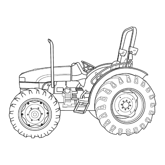
Page 25: Dimension
INTRODUCTION Dimension 56061233A NOTE: The following dimensions are based on standard tractors fitted with tire sizes as shown. Allowance must be given for tires of larger or smaller dimensions. 84269855 20/04/2010... - Page 26 NOTE: If your tractor has tires of a different size, then the above dimensions will vary due to the difference in the rolling radius and section width of the tires fitted. Tractor Total Weight Model WORKMASTER 75 (2WD) WORKMASTER 75 (FWD) On front axle 886 kg (1953 lb)
- Page 27 INTRODUCTION Engine Oil The correct engine oil viscosity grade is dependent upon ambient temperature. Refer to the chart on the right when selecting oil for your tractor engine. NOTE: In areas where prolonged periods of extreme tem- peratures are encountered, local lubricant practices are acceptable;...
-
Page 28: Product Identification
INTRODUCTION Product identification Tractor Identification Decal Location - Inside of Right-hand Center Panel The first line represents tractor serial number and model while the second line represents unit code and engine serial number followed by transmission serial number. Record the information in Figure 1 for quick reference. 20103294 Tractor Identification Location (Stamped) The tractor serial number, unit code, and engine number... - Page 29 SERVICE MANUAL HYDRAULIC - PNEUMATIC - ELECTRICAL - ELECTRONIC SYSTEMS Workmaster 75 84269855 20/04/2010...
- Page 30 PRIMARY HYDRAULIC POWER SYSTEM ..........A.10.A Workmaster 75 PRIMARY HYDRAULIC POWER SYSTEM Open center mechanical remote valve.
- Page 31 HYDRAULIC - PNEUMATIC - ELECTRICAL - ELECTRONIC SYSTEMS - A PRIMARY HYDRAULIC POWER SYSTEM - 10.A Workmaster 75 84269855 20/04/2010 A.10.A / 1...
- Page 32 Contents HYDRAULIC - PNEUMATIC - ELECTRICAL - ELECTRONIC SYSTEMS - A PRIMARY HYDRAULIC POWER SYSTEM - 10.A TECHNICAL DATA PRIMARY HYDRAULIC POWER SYSTEM General specification ............... 4 General specification for Implement attachments .
- Page 33 Service instruction ............... . . 45 Inspect .
-
Page 34: General Specification
HYDRAULIC - PNEUMATIC - ELECTRICAL - ELECTRONIC SYSTEMS - PRIMARY HYDRAULIC POWER SYSTEM PRIMARY HYDRAULIC POWER SYSTEM - General specification DESCRIPTION Lift Position control, draft control and combined Type position/draft control Control Independent lever(s) Lift sensitivity adjustment External four position lever on control valve Response adjustment Knob on control valve Single-acting cylinder:... -
Page 35: Torque
HYDRAULIC - PNEUMATIC - ELECTRICAL - ELECTRONIC SYSTEMS - PRIMARY HYDRAULIC POWER SYSTEM • under 3.60 - 4 kg (7.9 - 8.8 lb) 18 mm (0.71 in) Sensitivity adjustment pin lever outer spring length: 20.5 mm (0.81 in) • free •... -
Page 36: Sealing
HYDRAULIC - PNEUMATIC - ELECTRICAL - ELECTRONIC SYSTEMS - PRIMARY HYDRAULIC POWER SYSTEM PRIMARY HYDRAULIC POWER SYSTEM - Sealing 20098914 Operation Description Sealant Specification Lift Housing to Rear Axle Housing, (S1) ® 515 OCTITE Front Cover to Lift Housing, (S2) ®... -
Page 37: General Specification
HYDRAULIC - PNEUMATIC - ELECTRICAL - ELECTRONIC SYSTEMS - PRIMARY HYDRAULIC POWER SYSTEM Hydraulic pump - General specification Filter Type Paper cartridge Location On Pump Body, Suction Side Pump Type Gear, drawing from rear Transmission housing Location Behind timing cover Model Make Hema... -
Page 38: Torque
HYDRAULIC - PNEUMATIC - ELECTRICAL - ELECTRONIC SYSTEMS - PRIMARY HYDRAULIC POWER SYSTEM Hydraulic pump - Torque 20098843 Description Thread size Torque Nut, pump drive gear, (C1) 47.5 N·m (35.0 lb ft) 7/16 - 20 Nut, pump mounting on timing case, 8 N·m (5.9 lb ft) M6 x 1 (C2) -
Page 39: Component Identification Introduction And Circuit Identification
PRIMARY HYDRAULIC POWER SYSTEM - Component identification Introduction and circuit identification The hydraulic system on the WORKMASTER 75 tractor is for mechanical lift assembly to raise and lower the lift arms in turn three point linkages and for remote control valves. -
Page 40: Static Description
HYDRAULIC - PNEUMATIC - ELECTRICAL - ELECTRONIC SYSTEMS - PRIMARY HYDRAULIC POWER SYSTEM PRIMARY HYDRAULIC POWER SYSTEM - Static description Mounted on top of transmission housing comprising of following components: Position control lever, (1). • Draft control lever, (2) (optional). •... - Page 41 This as a preview PDF file from best-manuals.com Download full PDF manual at best-manuals.com...
Need help?
Do you have a question about the Workmaster 75 and is the answer not in the manual?
Questions and answers