
Subscribe to Our Youtube Channel
Related Manuals for Böcker TL 1512


Summary of Contents for Böcker TL 1512
- Page 1 Operating Manual Steel frame Table form lift TL 1512 Translation of the German original Doc. No.: 213300043 Before starting any work, read the operating manual!
- Page 2 Steel frame Table form lift TL 1512 © Böcker Maschinenwerke GmbH Lippestr. 69-73 59368 Werne, Germany Tel.: +49 (0) 2389 7989-0 Fax: +49 (0) 2389 7989-9000 email: info@boecker-group.com Website: www.boecker-group.com 213300043...
- Page 3 Steel frame Table form lift TL 1512 Layout of these instructions These assembly and operating instructions refer to... Doc. no.: 213300043 Original from: May 05, 2010 Version 26082015 ... applies to: Type Steel frame Table form lift Serial number: from 101...
-
Page 4: Table Of Contents
Incorrect use .................... 17 Danger zones ..................17 Design and function ................18 Overview ....................18 Sub-assemblies of the Table lift TL 1512 ..........20 Technical data ..................21 Technical data TL 1512 ................21 Electrical data TL 1512 ................21 Mechanical data TL 1512 ................. - Page 5 Steel frame Table form lift TL 1512 Ground station, next to the cable bin ............57 6.1.1 Pendant control panel at the ground station ..........59 Loading platform control system ............... 60 Loading point control system ..............62 Diagnosis system (Art. No. 2160000004) ..........64 Initial start up of the Table lift .............
-
Page 6: Foreword
the operation the safety instructions and servicesmaintenance of the steel frame Table form lift TL 1512, herein after referred to as ‘Table lift’. Before starting work read these operating instructions completely and observe the safety instructions to avoid damage to persons and property. -
Page 7: Liability And Warranty
Steel frame Table form lift TL 1512 1.1 Liability and warranty Guarantee and liability claims for damage to people or property will be excluded if they can be traced back to one or more of the following causes: Failure to observe the safety instructions and guidelines... -
Page 8: General Safety Instructions
Steel frame Table form lift TL 1512 2 General safety instructions 2.1 For the operator This operating manual must always be available at the site of operation. Reading and compliance by the loading platform operator and those persons charged with the assembly is mandatory. -
Page 9: Maintenance And Repairs
Steel frame Table form lift TL 1512 2.1.3 Maintenance and repairs Ensure that the deadlines for the legally required inspections and the intervals for inspection and maintenance defined in the operating manual are adhered to (see Chapter 11 ‘Maintenance’). -
Page 10: Explanation Of Signs/Safety Symbols
Steel frame Table form lift TL 1512 2.2 Explanation of signs/safety symbols For better understanding and easy recognition safety instructions are marked with these pictograms. In the text below we will introduce these pictograms and their meaning: DANGER! STOP This sign indicates danger to life and limb. - Page 11 Steel frame Table form lift TL 1512 In addition, we use pictogram in this manual that have been adapted to certain actions or a hazard situation. Example: DANGER! Risk of falling from heights! Never attempt to open the door to the loading platform or to the next building level while the lift is in motion.
-
Page 12: Safetysigns On The Table Lift
Steel frame Table form lift TL 1512 2.3 Safetysigns on the Table lift Brief operating instructions This note can be found on the loading platform near the control panel Fig. 1: Brief operating instructions Load capacity This note can be found on the loading platform near the control panel Fig. - Page 13 Steel frame Table form lift TL 1512 Anchor forces This note can be found on the loading platform near the control panel Fig. 3: Anchor forces Rated load capacity This note can be found on the loading platform near the control panel Fig.
- Page 14 Steel frame Table form lift TL 1512 Rating plate The type plate is on the drive unit and contains the following information: Type Manufacturing number Year of construction Alternating current max. lifting height in m ...
-
Page 15: Intended Use
Steel frame Table form lift TL 1512 2.4 Intended use The Table lift is a temporarily lifting system installed at construction sites. The system is compliant with the German BGV D7 § 2 (German Employer’s Liability Insurance Association). Depending on the requirements, the lift can be operated in one of the two operating modes. - Page 16 Steel frame Table form lift TL 1512 Only specially trained and qualified personnel shall be permitted to work on the Table lift (this applies especially to assembly, maintenance and repair work). These persons are defined by the end-user. ...
-
Page 17: Incorrect Use
Steel frame Table form lift TL 1512 2.5 Incorrect use Using the Table lift for any other purposes than those defined above are forbidden. Never use the lift as a crane. During this kind of improper use of the Table lift the lift can topple causing serious injuries to persons, damage to the Table lift or the building. -
Page 18: Design And Function
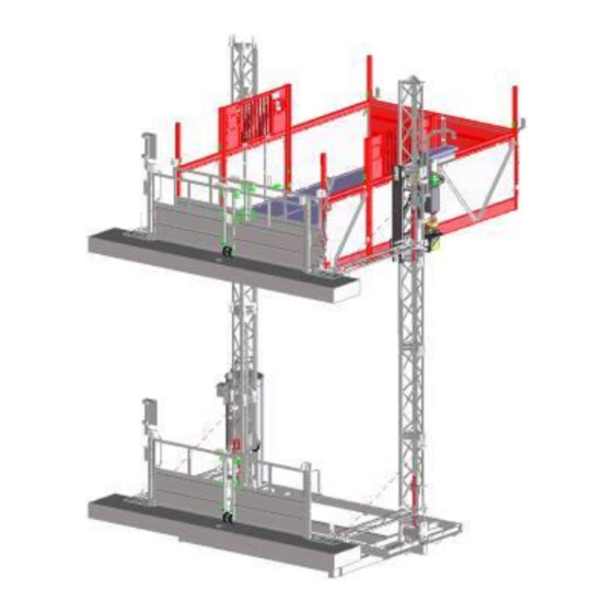
Steel frame Table form lift TL 1512 3 Design and function 3.1 Overview Fig. 7: Overall view 213300043... - Page 19 Steel frame Table form lift TL 1512 Fig. 8: Top view 213300043...
-
Page 20: Sub-Assemblies Of The Table Lift Tl 1512
Steel frame Table form lift TL 1512 3.2 Sub-assemblies of the Table lift TL 1512 Base frame 1. Base frame with buffer (not shown) and safety fence (optional) 2. Electrical cabinet on the base frame, next to the cable bin (not... -
Page 21: Technical Data
Steel frame Table form lift TL 1512 4 Technical data 4.1 Technical data TL 1512 Details Value Unit Rated load capacity 1685 kg max. 12 Persons Weight when loading max. 2370 kg Weight during installation max. 500 kg Rated speed... -
Page 22: Mechanical Data Tl 1512
Steel frame Table form lift TL 1512 Types of protection: Electrical cabinet/switches IP 54 and electrical components of the safety brake Movable control units IP65 Motors IP54 4.3 Mechanical data TL 1512 Details Value Unit Maximum lifting height without mast anchorage... -
Page 23: Environmental Conditions Tl 1512
Steel frame Table form lift TL 1512 4.5 Environmental conditions TL 1512 Details Value Unit Maximum allowable wind speed 80 km/h During assembly/dismantling 45 (12.5) (m/s) 80 km/h During operation 72 (20) (m/s) 80 km/h When idle/not in operation 160 (44.4) -
Page 24: Safety Devices
Steel frame Table form lift TL 1512 4.7 Safety devices Type of safety devices Location: Emergency lowering device Platform: Lever attached to the (manual venting) side of the motor Safety brake: Below the drive on the left-hand side. EMERGENCY OFF button:... -
Page 25: Emergency Off Button
Steel frame Table form lift TL 1512 4.7.1 Emergency off button CAUTION! In an emergency, use the EMERGENCY OFF button to stop the loading platform. When activating the EMERGENCY OFF button, it is locked and can only be unlocked after the malfunction is eliminated. -
Page 26: Safety Instructions For The Assembly Personnel
Steel frame Table form lift TL 1512 5 Table lift assembly At least two persons must be present when assembling the Table lift. 5.1 Safety instructions for the assembly personnel NOTE! When assembling the Table lift, utmost care and caution is required. Compliance with the work sequence instructions and the relevant safety information is mandatory. -
Page 27: Danger Zones
Steel frame Table form lift TL 1512 5.2 Danger zones A very dangerous zone is the area below the loading platform. Ensure all personnel remains outside of this area during the assembly work. DANGER! STOP Do not enter the area below the loading platform. -
Page 28: Selection Of Location
Steel frame Table form lift TL 1512 5.4 Selection of location Prior to the assembly, technical personnel must inspect and select the location the relevant construction site. 5.4.1 Location requirements Always select a level location for the base frame. -
Page 29: Support Forces ( In Kn)
Steel frame Table form lift TL 1512 5.4.2 Support forces ( in kN) Spindle H = Assembly height in meter 213300043... -
Page 30: Assembly Of The Base Frame
Steel frame Table form lift TL 1512 5.5 Assembly of the base frame Transporting the basic unit: (max. number of masts: 2 per side) Fig. 10: Basic unit with a transport traverse Fig. 11: Basic unit with a transport traverse... - Page 31 Steel frame Table form lift TL 1512 Attach the appropriate load cables to the mast component and use the transport vehicle to lift the basic unit. Place the basic unit on level ground according to the assembly diagram. There are several spindles with...
- Page 32 Steel frame Table form lift TL 1512 NOTE! The distance of the base frame from the ground must be at least 120 mm. This allows the use of the forklift for transporting purposes. (see Fig. 12: Spindles of a mast side)
-
Page 33: How To Assemble The Table Lift
Steel frame Table form lift TL 1512 5.6 How to assemble the Table lift Fig. 15: How to assemble the Table lift in front of a wall 213300043... -
Page 34: How To Assemble The Platforms
Steel frame Table form lift TL 1512 5.7 How to assemble the platforms 5.7.1 Using a forklift Attach the semi platform to the base frame. First, only tighten the bolts that are easily accessible. Base platform Semi platform Base frame Fig. - Page 35 Steel frame Table form lift TL 1512 Use the forklift to place the standard loading plat form and use of the flanges to attach the platform group (only tighten bolts that are easily accessible) Fig. 18: Position the standard loading platform Align the entire platform group and tighten bolts.
-
Page 36: Crane Assembly
Steel frame Table form lift TL 1512 5.7.2 Crane assembly During the assembly of the crane, work steps 1, 2 and 3 of the forklift assembly are omitted. The platform is assembled completely. Subsequently, the crane is used to align and tighten all connections. -
Page 37: Safety Instructions
Steel frame Table form lift TL 1512 sus pended l oads 5.7.3 Safety instructions DANGER! STOP Sudden start-ups of the Table lift bear the inherent danger of life-threatening injuries. During assembly work outside of platform, in particular while working on the mast or the mast... - Page 38 Steel frame Table form lift TL 1512 Press the EMERGENCY OFF button of the platform control panel Open the installation hatch of the loading platform Fig. 21: Installation hatch for the mast assembly NOTE! The Table lift comes with a pre-assembled mast component. It contain s already the limit switch contact plate for the ground station.
- Page 39 Steel frame Table form lift TL 1512 Fig. 22: Threaded mast connections Close the installation hatches again. Subsequently, the limit switches behind the hatches will enable the Table lift to continue its travel. Place the next mast components onto the platform.
-
Page 40: Mast Anchorage
Steel frame Table form lift TL 1512 5.9 Mast anchorage 5.9.1 Observe anchor forces Depending on the configuration the lift and anchor types used at the specific construction site, the anchor forces can vary considerably and must be verified for each Table lift system. - Page 41 Steel frame Table form lift TL 1512 Anchor forces Fig. 23: Anchor forces when anchoring in front of the building wall 213300043...
-
Page 42: Mast Anchor Set, Incl. Support For Floor Gate
Steel frame Table form lift TL 1512 CAUTION! The spacing of the mast anchors between the mast and the building m u s t not exceed a distance of 9 m. NOTE! Ensure the masts are perpendicular to the building wall. - Page 43 Steel frame Table form lift TL 1512 Align the anchor plate (4) and connector (1) (ensure they are parallel to the platform) At the height of the first floor, attach the connector (1) to the mast. Pin the mast anchor pipe (2) to the connector (1) (rotate 1 and 2 to the outside;...
- Page 44 Steel frame Table form lift TL 1512 5.9.2.1 Mast anchorage - other variants split anchor plates/floor gate support Mast anchor without floor gate support Use floor anchors to attach the anchor plate In order to attach the anchor plate we recommend the anchor type below: Fischer mounting system –...
- Page 45 Steel frame Table form lift TL 1512 Mast anchor in front of wall (without floor gate support) Use floor anchors to attach the anchor plate In order to attach the anchor plate we recommend the anchor type below: Fischer mounting system – Anchor bolt FAZ II 12/30 GS...
-
Page 46: Installation Of The Cable Guides
Steel frame Table form lift TL 1512 5.10 Installation of the cable guides In order to ensure that the trailing cable can be safely moved without getting caught, cable guides must be installed at the operating side of the mast. -
Page 47: Inserting The Bin Cable
Steel frame Table form lift TL 1512 5.11 Inserting the bin cable Always insert the bin cable in a clockwise motion; otherwise kinks will form and the cable may be damaged. Fig. 29: Inserting the bin cable 5.12 Installation of the Table lift’s switch cabinet... - Page 48 Steel frame Table form lift TL 1512 Illustration of the assignment of the fold-down ramp monitoring Fig. 31: Bottom view of switch cabinet 213300043...
-
Page 49: Installation Of The Floor Limit Switch And The Mast Limit Switch
Steel frame Table form lift TL 1512 5.13 Installation of the floor limit switch and the mast limit switch Install the upper limit switch plate > 1.58 m below the top of the mast. Fig. 32: Installation of the upper limit switch plate... - Page 50 Steel frame Table form lift TL 1512 Fig. 35: Ramp support area on the building CAUTION! The ramp of the lift must always sit horizontally on the edge of the building! (see Fig. 35: Ramp support area on the , page 50)
- Page 51 Steel frame Table form lift TL 1512 CAUTION! All dimensions must be maintained Install the upper limit switch plate > 1.58 m below the top of the mast. Distance of the floor limit switch’s actuating cam to the upper limit switch plate >...
-
Page 52: Testing The Safety Brake
Steel frame Table form lift TL 1512 5.14 Testing the safety brake After the installation has reached a height of 6 - 8 m, the safety brake must be tested. In order to do this, proceed as described below: ... -
Page 53: Installation Of The Base Enclosure (Optional)
Steel frame Table form lift TL 1512 5.15 Installation of the base enclosure (optional) Secure the lower hazard zone by installing an enclosure, 1.10 m high. The clearance between the enclosure and any moving parts of the lift must be at least 0.5 m. -
Page 54: Installation Of The Loading Point Gates
Steel frame Table form lift TL 1512 5.16 Installation of the loading point gates CAUTION! A landing gate must be installed at each loading point (access point) which must be secured compliant with EN 12158-1. Only those loading point gates approved by the manufacturer are permitted. - Page 55 Steel frame Table form lift TL 1512 The following applies: Use 2 Fischer anchor bolts for each Wall anchor plate Floor 213300006 - Mast anchor in front of gate building wall without support for floor Edge of hinged floor gate gate.
-
Page 56: Cable Routing At The Loading Point Gates
Steel frame Table form lift TL 1512 5.16.1 Cable routing at the loading point gates Cable routing at the pivoting gate (platform) Cable routing at the first loading point Blind plug, if there are no further floors Cable routing at the last loading point... -
Page 57: Buttons Of The Table Lift
Steel frame Table form lift TL 1512 6 Buttons of the Table lift The Table lift can be operated from several locations: form the pendant control station at the ground station (during material transport from the outside of the lift) ... - Page 58 Steel frame Table form lift TL 1512 Secure the lift to prevent accidental restart The EMERGENCY OFF switch is a rotary switch and can be activated and locked as shown inFig. 44 Fig. 44: Activation of the EMERGENCY OFF main switch...
-
Page 59: Pendant Control Panel At The Ground Station
Steel frame Table form lift TL 1512 6.1.1 Pendant control panel at the ground station Fig. 45: Pendant control panel at the ground station. How to operate the pendant control panel The pendant control panel can be used to activated the lift if the... -
Page 60: Loading Platform Control System
Steel frame Table form lift TL 1512 6.2 Loading platform control system During the assembly of the mast and in order to transport personnel, the Table lift is activated from the platform. Fig. 46: Using the rotary switch to control the platform Operating buttons of the platform control system Position Fig. - Page 61 Steel frame Table form lift TL 1512 Switch position Designation Function Activation of the lift only possible from Outside the outside Lift activation not possible Activation of the lift possible from the inside and outside. In this instance, the Automatic mode...
-
Page 62: Loading Point Control System
Steel frame Table form lift TL 1512 6.3 Loading point control system 1 = Stop at next floor 2 = UP 3 = DOWN 4 = Stop button 5 = Connection for next loading position Fig. 47: Loading point control system Position Fig. - Page 63 Steel frame Table form lift TL 1512 NOTE! Button (1) “Stop at next floor” is active while material and personnel are transported. From the load position control stations, the platform can only be moved to the 2-meter zone. After reaching this height, the platform can only be activated from the pendant control station at the ground.
-
Page 64: Diagnosis System (Art. No. 2160000004)
Steel frame Table form lift TL 1512 6.4 Diagnosis system (Art. No. 2160000004) NOTE! All illustrated malfunction refer to a machine with integrated diagnosis system Error message and troubleshooting US = User LO = Lift operator TE = Technician 213300043... - Page 65 Steel frame Table form lift TL 1512 Malfunction Error message Possible cause Troubleshooting: Repair by CODE* “Floor” safety circuit a) The Emergency Off a) Unlock button a) US button was activated b) The Emergency Off button on one of the...
- Page 66 Steel frame Table form lift TL 1512 Malfunction Error message Possible cause Troubleshooting: Repair by CODE* Emergency limit a) Lift is too low in the b) Return lift from recovery a) LO mode to entry level height. switch bottom emergency limit...
- Page 67 Steel frame Table form lift TL 1512 Malfunction Error message Possible cause Troubleshooting: Repair by CODE* Side door ‘C’ a) Door ‘C’ is not a) Close door ‘C’ properly a) US properly closed b) Connector of door b) Plug in connector of door a) US ‘C’...
- Page 68 Steel frame Table form lift TL 1512 Malfunction Error message Possible cause Troubleshooting: Repair by CODE* NO11 Ini. Mast a) Lift raised too high! a) Move lift down and install b) TE Lift outside of its normal limit switch plate in mast...
-
Page 69: Initial Start Up Of The Table Lift
Steel frame Table form lift TL 1512 7 Initial start up of the Table lift 7.1 General safety instructions regarding the initial start-up DANGER! STOP Improper operation may lead to life-threatening injuries A rack and pinion lift develops great forces when travelling up as well as down. -
Page 70: Protective Measures In The Event Of High Wind Speeds
Steel frame Table form lift TL 1512 7.2 Protective measures in the event of high wind speeds All personnel must leave the lift immediately. Lower the platform to the ground station. Switch the Table lift off and secure the switch to prevent accidental restart. -
Page 71: Switching On The Table Lift
Steel frame Table form lift TL 1512 7.3.2 Switching on the Table lift Open the pad lock on the EMERGENCY OFF master switch (if available). Unlock the external EMERGENCY OFF button (if previously activated). Turn on the EMERGENCY OFF master switch. -
Page 72: How To Operate The Table Lift
Steel frame Table form lift TL 1512 8 How to operate the Table lift 8.1 Safety instructions for the operation of the Table lift 8.1.1 Safety instructions for the platform operator Prior to starting work on the lift, proceed with a safety check of the Table lift. -
Page 73: Safety Instructions For Personnel Travelling On The Platform
Steel frame Table form lift TL 1512 8.1.3 Safety instructions for personnel travelling on the platform DANGER! STOP Improper behavior may cause life-threatening injuries Compliance with the instructions by the platform supervisor are mandatory. While travelling on the lift, do not lean over platform gates. -
Page 74: Transport Of Personnel
Steel frame Table form lift TL 1512 8.2 Transport of personnel During the operating mode "Person transport", the platform must only be operated from the platform by an operator who is named by the owner and authorised. The hatched area must never be occupied by personnel. - Page 75 Steel frame Table form lift TL 1512 NOTE! The platform is operated in inching mode; this means, if the rotary switch is turned to the right or left, the platform travels in the applicable direction. If the operating button is released, the platform stops.
-
Page 76: Entering The Ground Station (2-M Area)
Steel frame Table form lift TL 1512 8.2.1 Entering the ground station (2-m area) Important note for the platform operator CAUTION! When approaching the ground station, the platform stops 2 m above the ground; a signal is sounded, lasting approx. 3 seconds. -
Page 77: Transport Of Material
Steel frame Table form lift TL 1512 8.3 Transport of material Set switch position to “Außen” (Outside), remove key During this operating mode the transport of personnel is prohibited. A pendant control panel is used to operate the platform from the ground station or from the load position control, if available. -
Page 78: Illustration Of Loading Points
Steel frame Table form lift TL 1512 8.3.1 Illustration of loading points 213300043... - Page 79 Steel frame Table form lift TL 1512 Illustration of loading points loading point load (kg) quantity pallet cage/stacking frame size pallet cage/stacking frame 120x80 120x80 120x160 240x80 180x180 120x80 213300043...
-
Page 80: Transporting The Slap Frameworks
Steel frame Table form lift TL 1512 8.3.2 Transporting the slap frameworks Move the slap framework to the specified mechanical stop (see Fig. 48) and secure it to prevent slipping. Attachment Fig. 48: Attachments on platform (top view) CAUTION! EJB 213 EHW-table... -
Page 81: Please Note! Entering The Ground Station (2-M Area)
Steel frame Table form lift TL 1512 8.3.3 Please note! Entering the ground station (2-m area) CAUTION! When approaching the ground station, the platform stops 2 m above the ground. Subsequently, the material can only be transported in dead man’s mode via the pendant control panel at the ground station. -
Page 82: How To Operate The Door Locking Mechanism - Platform Gate System
Steel frame Table form lift TL 1512 8.4 How to operate the door locking mechanism – Platform gate system Regardless what operating mode the platform is in, all locking systems are effective in the same way. 8.4.1 Opening the loading ramp If the loading ramp must be opened, the transport platform must have come to complete halt on one of the loading positions. - Page 83 Steel frame Table form lift TL 1512 Ramp support bracket Fig. 51: Ramp support area on the building CAUTION! Fold down the ramp (must be folded down until it contacts the ramp support bracket) CAUTION! The ramp of the lift must always sit horizontally on the edge of the building!
-
Page 84: Door Locking Mechanism Of The Pivoting Gate
Steel frame Table form lift TL 1512 8.4.2 Door locking mechanism of the pivoting gate In order to open the pivoting gate, the following conditions must be met: The pivoting gate can only be opened if the loading ramp is open. -
Page 85: How To Act In The Event Of Emergencies
Steel frame Table form lift TL 1512 10 How to act in the event of emergencies In this chapter we describe how to act in the event of emergencies or other exceptional situations. NOTE! If you have any further questions, please contact the manufacturer. - Page 86 Steel frame Table form lift TL 1512 Safety instructions for the platform operator DANGER! STOP The Table lift offers you various possibilities for reacting to emergencies. Please be aware that this manual can only give you suggestions for the correct technical procedure in emergency situations.
-
Page 87: Emergency Off Button
Steel frame Table form lift TL 1512 10.1.1 Emergency Off button DANGER! STOP In an emergency, use the EMERGENCY OFF button to stop the loading platform. When activating the EMERGENCY OFF button, it is locked and can only be unlocked after the malfunction is eliminated. -
Page 88: Activation Of The Safety Devices
Steel frame Table form lift TL 1512 10.2 Activation of the safety devices 10.2.1 Important instructions for the platform operator Due to a technical problem or as a result of an emergency, the control system may render the Table lift inoperable and stops while in person transporting mode and while personnel is occupying the platform. - Page 89 Steel frame Table form lift TL 1512 Technical emergency Effects Possible emergency operation per: The cable break limit switch Rescue control (only in downward Travel cannot continue. While the (optional) shuts off while the table motion) lift travels up, the trailing cable is in upward motion.
-
Page 90: Rescue Control (Only By Technical Personnel)
Steel frame Table form lift TL 1512 10.2.2 Rescue control (only by technical personnel) The rescue control system is one option to operate the Table lift briefly after a malfunction and to move the platform to next loading position. NOTE! The rescue control system allows only to move the Table lift upward. -
Page 91: Using Manual Venting To Lower The Platform (Only By Technical Personnel)
Steel frame Table form lift TL 1512 Turn the operating mode selection switch from the normal position to the rescue position. Press the control button on the right-hand side of the rotary switch. As long as the button is pressed, the platform move up. - Page 92 Steel frame Table form lift TL 1512 Switch the Table lift off and secure the switch to prevent accidental restart. Place on person on the right- hand side and one person on the left-hand side of the platform. Carefully press the manual venting lever of the drive until the platform is slowly put in motion.
-
Page 93: Rescuing Personnel
Steel frame Table form lift TL 1512 10.2.4 Rescuing personnel If the platform stops during its drive and cannot be restarted, all personnel occupying the platform must be rescued. DANGER! STOP During the rescue attempt, the approaching platform can cause fatal injuries. -
Page 94: Disassembling The Lift
Steel frame Table form lift TL 1512 10.3 Disassembling the lift The lift is disassembled in the reverse order of the assembly procedure CAUTION! Only properly trained personnel shall be permitted to proceed with the disassembly. 213300043... -
Page 95: Maintenance And Care
Steel frame Table form lift TL 1512 11 Maintenance and care NOTE! The owner is responsible to have only knowledgeable and trained technicians to proceed with the maintenance. Otherwise, all warranties shall be deemed null and void. 11.1 Maintenance safety instructions... -
Page 96: After The Maintenance/Repair
Steel frame Table form lift TL 1512 DANGER! STOP There is an inherent risk of fatal injuries when replacing larger sub-assemblies When replacing larger sub-assemblies, use hoisting equipment to attach and secure them. Improperly secured components can drop to the ground and cause life-threatening injuries or damage to property. -
Page 97: Maintenance Plan
Steel frame Table form lift TL 1512 11.3 Maintenance plan In the following section the maintenance tasks necessary for an optimal and trouble free operation are described. If an increase in wear and tear is detected during the regular inspections the maintenance intervals should be shortened according to the actual signs of wear. - Page 98 Steel frame Table form lift TL 1512 Interval Description Task Comment To be performed by Emergency limits switch Check function Customer top/bottom service technician every 3 Emergency limits switch Customer Check function months top/bottom service technician Inductive limit switch on...
- Page 99 Steel frame Table form lift TL 1512 Interval Description Task Comment To be performed by Safety brake Conduct a brake test After the safety brake Customer was triggered, the service respective mast area technician and the relevant mast screws must be inspected for external damage.
-
Page 100: Maintenance And Care Of The Motor Brakes (Zfb 62 So)
Steel frame Table form lift TL 1512 11.3.1 Maintenance and care of the motor brakes (ZFB 62 So) Fig. 59: ZFB brake Overall size ZFB 60 Working air gap Max. air gap A max. Stroke limitation Minimum thickness of the 11.5... - Page 101 Steel frame Table form lift TL 1512 11.3.1.1 Re-adjusting the brakes CAUTION! When working on the brakes, the power must be disconnected and accidental re-start must be prevented. When working on the brake motor, the cool air ducts must be kept clean and monitor the air gap.
-
Page 102: What To Do If
Steel frame Table form lift TL 1512 12 What to do if ... Tips and important information about malfunctions and events that may occur during the initial start-up of the operation. Only a qualified electrician shall be permitted to proceed with tasks on electrical systems and operating equipment. - Page 103 Steel frame Table form lift TL 1512 Description of malfunction Cause of the malfunction Actions taken Operational limit switch TOP is Check the limit switch. Replace if defect or has become maladjusted. necessary. The lift does not move when the...
-
Page 104: Beaufort Scale
Steel frame Table form lift TL 1512 Operati on 13 Beaufort scale Description Speed Effects acc. to Beaufort m/s / km/h inland 0-0.2 / <1 Smoke rises vertically No wind Smoke drift indicates wind 0.3-1.4 / 1-5 Light draught direction Wind felt on exposed skin. -
Page 105: Screw Tightening Torque
Steel frame Table form lift TL 1512 14 Screw tightening torque CAUTION! Self locking nuts, cotter pins, and clamping pins must be replaced after each removal. Always use a torque wrench when checking the torque of threaded components. -
Page 106: Test Inspection For Expert Checks
Steel frame Table form lift TL 1512 15 Test inspection for expert checks The inspection depends on the national regulations In Germany the inspection duties for the end-user/user are defined in the Betriebssicherheitsverordnung (Regulation for operational safety) Test results based on the German Betriebssicherheitsverordnung On ____________________the Table lift, manufacturing number _______ was subject to a visual inspection and function test. - Page 107 Steel frame Table form lift TL 1512 Test inspection for expert checks The inspection depends on the national regulations In Germany the inspection duties for the end-user/user are defined in the Betriebssicherheitsverordnung (Regulation for operational safety) Test results based on the German Betriebssicherheitsverordnung On ____________________the Table lift, manufacturing number _______ was subject to a visual inspection and function test.
- Page 108 Steel frame Table form lift TL 1512 Test inspection for expert checks The inspection depends on the national regulations In Germany the inspection duties for the end-user/user are defined in the Betriebssicherheitsverordnung (Regulation for operational safety) Test results based on the German Betriebssicherheitsverordnung On ____________________the Table lift, manufacturing number _______ was subject to a visual inspection and function test.
- Page 109 Steel frame Table form lift TL 1512 Test inspection for expert checks The inspection depends on the national regulations In Germany the inspection duties for the end-user/user are defined in the Betriebssicherheitsverordnung (Regulation for operational safety) Test results based on the German Betriebssicherheitsverordnung On ____________________the Table lift, manufacturing number _______ was subject to a visual inspection and function test.
-
Page 110: List Of Installation Places Of Manufacturing Number
Steel frame Table form lift TL 1512 16 List of installation places of manufacturing number ..Layout Date from : to : 20 . . Place of operation :............. . . - Page 111 Steel frame Table form lift TL 1512 Layout Date from : to : 20 . . Place of operation :............. . .
- Page 112 Steel frame Table form lift TL 1512 Layout Date from : to : 20 . . Place of operation :............. . .
-
Page 113: Appendix
Steel frame Table form lift TL 1512 17 Appendix 17.1 Lift truck data sheet EJB 213 EHW Table 213300043... - Page 114 Steel frame Table form lift TL 1512 213300043...
- Page 115 Steel frame Table form lift TL 1512 Technical data of standard model Technical data according to VDI 2198. Subject to technical change without notice Performance data of standard vehicles Description EJB 213 Nominal load capacity 1250 Distance of center of gravity for standard fork length...
Need help?
Do you have a question about the TL 1512 and is the answer not in the manual?
Questions and answers