Table of Contents
Advertisement
Quick Links
FOREWORD
This vehicle has been designed and produced utilizing Suzuki's most modern tech-
nology. The finest product, however, cannot perform properly unless it is correctly
assembled and serviced. This set-up manual has been produced to aid you in prop-
erly assembling and servicing this vehicle.
Please review this set-up manual carefully before performing any work. Take special
care to properly perform the required assembly and servicing marked by either a
Warning or a Caution. Failure to follow the directions in either of these two (2) cate-
gories could lead to serious problems.
and
areas are
denoted to emphasize certain areas and carry the following meanings:
Indicates a potential hazard that could result in death or injury.
Indicates a potential hazard that could result in vehicle damage.
This set-up manual is based on a vehicle of standard specification. Some minor dif-
ferences from this manual may be found in other specifications.
K5
99505-01125-01E
September '04 Printed in Japan (TK) 28
Advertisement
Table of Contents

Subscribe to Our Youtube Channel
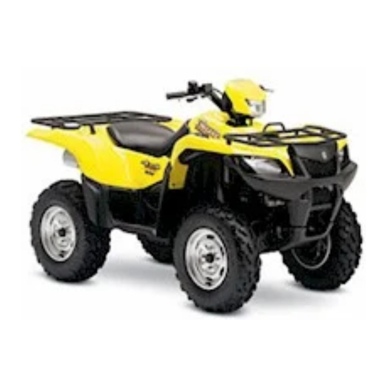
Related Manuals for Suzuki LT-A700XK5


Summary of Contents for Suzuki LT-A700XK5
- Page 1 FOREWORD This vehicle has been designed and produced utilizing Suzuki’s most modern tech- nology. The finest product, however, cannot perform properly unless it is correctly assembled and serviced. This set-up manual has been produced to aid you in prop- erly assembling and servicing this vehicle.
- Page 2 UNCRATING THE VEHICLE FRONT REAR Remove the carton. Remove the bolts and brackets. NOTE: The brackets, bolts and vinyl tube are no longer needed and these may be discarded. A: Bolt B: Bracket C: Vinyl tube Loosen the front brake master cylinder mounting bolts. Remove the master cylinder from the bracket.
-
Page 3: Location Of Parts
LOCATION OF PARTS Check off each of the components as shown in the photograph. - Page 4 Item Part Name Q’ty Remarks Item Part Name Q’ty Remarks Headlight assembly Wheel center cap Flange bolt 8 × 12 mm Mud guard rear fender Right and Left Spacer L:11 Fastener (Large) Allen bolt 5 × 20 mm Reflex reflector Headlight cover (Upper) Flange nut 5 mm...
- Page 5 The photograph shown indicates the parts dismounted from the model in addition to the items shown in the preceding page. A: Handlebar assembly B: Front brake master cylinder C: Ignition switch D: Meter assembly E: Front brake switch lead wire F: Wiring harness Before assembling the vehicle, thoroughly under- stand the “Safety Check Out”...
-
Page 6: Front Brake Master Cylinder
Tighten the handlebar clamp bolts to the specified torque. NOTE: To install the handlebars correctly, first tighten the bolt A A A A of the front side with specified torque and then tighten the bolt B B B B of the rear side. FORWARD Make sure that the clamp has no clearance at the front side as shown in the illustration. - Page 7 NOTE: Install the holder in position according to the mark “UP”. Make sure that the holder has no clearance at the upper side as shown. Check for brake fluid leakage. A: Bolt B: Holder C: Master cylinder D: Handlebars Connect the front brake light switch lead wires coupler to the brake light switch.
- Page 8 The line drawings on page 28, 29, 30 and 31 show the proper routing of the control cables, hose and wirings. Refer to them in addition to following the instructions carefully. A: Throttle cable B: Front brake hose C: Front brake switch lead wire D: 2WD/4WD DIFF LOCK selection switch wiring harness E: Rear brake lever cable F: Rear brake switch lead wire...
- Page 9 Install the meter assembly to the headlight brace. A: Meter assembly B: Boss C: Rubber grommet D: Meter wiring harness E: 5 × 20 mm allen bolt F: Spacer L:11 mm HEADLIGHT COVER AND METER COVER Fit the meter rubber cushion to the meter cover. A: Meter cover B: Meter rubber cushion Align the boss of the ignition switch to the meter cover...
- Page 10 Align the meter cover to the headlight brace. A: Headlight brace B: Meter cover Align the meter assembly with meter rubber cushion. Take care so that the rubber cushion is not pro- truded. A: Meter assembly B: Meter rubber cushion Fix the meter cover using fastener.
- Page 11 Align the boss and hook of headlight cover to the hole of headlight brace. A: Headlight cover B: Boss C: Hook D: Meter cover E: Hole Fit the headlight cover to the meter cover. A: Headlight cover B: Meter cover Fix the meter cover with the tapping screws.
- Page 12 Fix the headlight cover using fasteners. NOTE: To install the fastener, pull the center pin as C C C C and fix the fastener by pushing the center pin as D D D D . A: Headlight cover B: Fastener (Medium) 1.
- Page 13 WHEEL CENTER CAP Attach the wheel center cap. A: Wheel center cap B: Wheel C: Hub nut D: Washer TRAILER TOW BRACKET Install the trailer tow bracket. NOTE: Install the bracket placing its UP mark faced upward. Trailer tow bracket mounting bolt: 60 N·m (6.0 kgf-m) A: Trailer tow bracket B: 10 ×...
- Page 14 MUD GUARD REAR FENDER (FOR E-17, 24 MARKET) Check that the cushion is stuck to the correct position. NOTE: Stick the cushion on the end of radius. A: Cushion B: Mud guard rear fender Reflex Reflector (For E-17 market) Align the boss of reflex reflector to the hole of mud guard rear fender.
- Page 15 WARNING LABEL (FOR E-17 MARKET) Select the appropriate language label for your country. NOTE: For E-17 CG selection: German, Spanish, Portuguese For E-17 CH selection: French, Dutch For E-17 CI selection: Swedish, Finnish, Danish FRONT (RIGHT) Stick the label selected for your country. A: Warning label (General warning) B: Warning label (Tire information) C: Warning label (Age 16)
- Page 16 REAR (LEFT) FUEL LABEL (FOR LIMITED MARKET) Stick the label on the rear fender. A: Rear fender (Left) B: Fuel label BATTERY HOLDER AND BATTERY Install the battery holder and battery after the servicing of the battery is completed. A: Battery holder B: 6 ×...
- Page 17 SERVICING BATTERY Filling electrolyte Remove the aluminium tape sealing the battery elec- trolyte filler holes. A: Aluminium tape B: Electrolyte filler hole Remove the caps from the electrolyte container. NOTE: Use the removed caps as the sealed caps of battery filler holes. Do not remove or pierce the sealed areas of the electrolyte container.
- Page 18 Make sure air bubbles are coming up in each electro- lyte container, and leave in this position for about 20 minutes. A: Air bubbles NOTE: If no air bubbles are coming up from a filler port, tap the bottom of the container two or three times.
- Page 19 Charge the battery with a battery charger. For charging the battery, make sure to use the charger specially designed for MF battery. Otherwise, the battery may be overcharged resulting in shortened service life. Do not remove the cap during charging. Position the battery with the cap facing upward during charging.
-
Page 20: Brake Fluid
Install the battery holder. A: Battery holder B: 6 × 16 mm flange bolt Reinstall the seat. Insert the seat hook into the seat hook retainer and push the seat down firmly. A: Seat assembly B: Seat hook C: Seat hook retainer BRAKE FLUID Keep the vehicle upright and place the handlebars straight. -
Page 21: Throttle Cable
BRAKE AIR BLEEDING Any air which may have been trapped in the brake fluid circuit must be bled completely. If the brake lever feels spongy or weak, then most likely there is air in the hydraulic circuit. To bleed the air from the front brake, use the following procedure: 1. - Page 22 REAR/PARKING BRAKE Adjust the rear brake by adjusting the brake pedal first and then adjust the brake lever. The rear brake lever and rear brake pedal oper- ate the rear brake in a complementary manner. When one of these is misadjusted, the brake system as a whole will not operate properly.
- Page 23 Brake Lever (Parking Brake) Check the brake lever play at the lever holder when the lever is lightly pulled in towards the grip. Rear brake (Parking brake) lever play: 6.0–8.0 mm If adjustment is necessary, carry out the procedure below: 1.
- Page 24 TIRE PRESSURE Using an accurate air gauge, check the air pressure of the front and rear tires. The pressure should be as shown. COLD INFLATION TIRE PRESSURE TIRE PRESSURE LOAD FRONT REAR 35 kPa 30 kPa Up to 172 kg 0.35 kgf/cm 0.30 kgf/cm 380 lbs...
-
Page 25: Engine Coolant
ENGINE COOLANT The engine coolant level should be kept between the “FULL” and “LOW” level lines as shown in the photo- graph. Inspect the level with the vehicle held upright on level ground. A: Engine coolant reservoir B: “FULL” level line C: “LOW”... -
Page 26: Front Differential Gear Oil
FRONT DIFFERENTIAL GEAR OIL Place the vehicle on a level ground. Check the front differential gear oil levels as follows. Remove the oil level bolt. If the oil level is below the level hole, add the gear oil through the filler hole until the oil flows out from the level hole. - Page 27 Check the engine oil level with the engine oil dipstick. 1. Place the vehicle on level ground. 2. Start the engine and allow it to run for a few minutes at idling speed. Stop the engine and wait about three minutes. 3.
-
Page 28: Tightening Torque
TIGHTENING TORQUE Item Part Name N·m kgf-m Item Part Name N·m kgf-m STEERING, FRONT SUSPENSION AND FRONT BRAKE REAR SUSPENSION AND REAR BRAKE Handlebar clamp bolt Rear shock absorber mounting nut (upper) Handlebar holder nut Rear shock absorber mounting nut Front hub nut 11.0 (lower) -
Page 29: Cable Routing
CABLE ROUTING Frame Throttle cable Parking brake cable Wiring harness Parking brake cable Frame Parking brake cable Location of cable and harness: as shown Wiring harness Parking brake cable Parking brake cable guide Fix the foot brake cable to the footrest bar Handlebar Boss Locate the throttle cable as shown. - Page 30 Wiring harness Parking brake cable Rear fender Parking brake cable Tie the protector with clamp as shown. Screw Frame Frame Protector Parking brake cable Rear fender Parking brake cable Fix the foot brake cable Adjust nut to the footrest bar Rear brake assy Foot brake cable...
-
Page 31: Harness Routing
HARNESS ROUTING Set the sag under combination meter Front brake switch lead wire 2WD/4WD DIFF LOCK selection switch lead wire Pass the combination meter wire to behind the upper bracket. Clamp Fix the front brake hose. Clamp Horn switch lead wire (E-17, 24) Emergency switch lead wire (E-17) Handlebar switch lead wire (L) Parking brake switch lead wire... - Page 32 Clamp Wiring harness Wiring harness Clamp Clamp Clamp Wiring harness Reservoir hose Cooling fan thermo switch lead wire Brake/taillight lead wire Wiring harness Wiring harness Wiring harness Back lamp relay lead wire (E-17) Clamp Clamp Clamp Clamp Clamp Wiring harness ISC valve Injector coupler Clamp...
-
Page 33: Safety Check-Out
SAFETY CHECK OUT COLD INFLATION TIRE PRESSURE TIRE PRESSURE After completion of the setting-up the vehicle LOAD FRONT REAR all the following items should be double- 35 kPa 30 kPa checked to confirm that the operation and func- Up to 172 kg 0.35 kgf/cm 0.30 kgf/cm 380 lbs...
Need help?
Do you have a question about the LT-A700XK5 and is the answer not in the manual?
Questions and answers