
Related Manuals for Barton Musical Circuits BMC018.Analog Drum


Summary of Contents for Barton Musical Circuits BMC018.Analog Drum
- Page 1 BMC018. Analog Drum. Last updated 12-27-2020 I Features II Schematics A.Master Schematic. B.Input/Decay C.VCO D.VCA E.Power Connections. III Construction A.Parts List B.The Board...
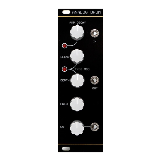
- Page 2 I. Features This module is an analog drum sound. It was designed to be built using a minimum of parts and no difficult to obtain parts. I initially was only trying to build a "disco tom" type sound, but I'm more impressed with it's bass-drum like sounds.
- Page 4 INPUT/DECAY On the far left we see the wirepad marked "IN." A trigger or gate signal should be input here. The .01uf capacitor and 100K resistor to ground form a pulse shortener, making the pulse length of the input signal irrelevant.
- Page 5 On the far left we see the output of the decay section for amplitude. A single 2n3906 in series with a 10k resistor forms the current control. This VCA is incredibly simple, the signal is input to the inverting input through a 22K and 220 ohm resistor voltage divider used to limit the signal on the input.
- Page 6 Parts List Semiconductors Value Qty Notes TL074 LM13700 or 13600 2N3906 1N4148 Resistors Value Qty Notes 10 ohm 7.5mm lead spacing 220 ohm " " 470 ohm " " 1K ohm " " 4.7K " " " " " " "...
- Page 7 Jacks Either 1/4" or 1/8" Knobs The Board The PCB is 100mm x 41mm. The pots are spaced 21mm apart. The mounting holes are spaced 91mm x 29mm. I've highlighted a few key resistors that a builder may want to modify. The yellow resistors control the brightness of the LEDs.
- Page 8 Below is an image of the PCB with traces included to help when troubleshooting. The ground plane is not depicted, so assume pads with no connection are connected to ground: Installing LEDs Sideways The PCB indicates that the LEDs should be mounted parallel to the board, do not do this. Leds should be pointing in the same direction as the pots.
Need help?
Do you have a question about the BMC018.Analog Drum and is the answer not in the manual?
Questions and answers