
Related Manuals for Barton Musical Circuits BMC58


Summary of Contents for Barton Musical Circuits BMC58
- Page 1 BMC58. Yes No Maybe Sequencer last updated August 28 , 2019 I. Using The Module A. What does this do? B. Controls C. Changing Modes II. Schematic A. Master Schematic B. Switches C.Inputs D.Outputs III. Construction A.Parts List B.PCB Information...
-
Page 2: Using The Module
I.Using The Module A. What does it do? This sequencer outputs an 8 or 16 step pattern. Each step has a toggle that can set the output definitely on (YES), definitely off (NO) or maybe on or off (MAYBE). The probability of an output being on can be controlled with the MAYBE knob and MAYBE CV input. - Page 3 II. Schematic A. Master Schematic Above is the master schematic. It comprises both PCBs. The components on the Top PCB have a blue background and the components on the bottom PCB have a yellow background. On the next pages, I'll show different sections of the project in easier to follow bits. You may notice that the master schematic shows a 10K resistor bus, in the following schematics, these will be shown as 10K resistors.
- Page 4 B. Switches Above are the toggles, LEDs and the circuitry that controls it. On the far left of the image is the CD4051 CMOS switch. Pins 9, 10 and 11 of this are connected to the PIC, which controls which of the output pins connects to ground. Each output pin is connected to two LEDs and two switching diodes connected to the center of an ON/OFF/ON SPDT toggle.
- Page 5 C.Inputs To the right are the inputs for the module. On the top left, we see the Maybe and Maybe CV pots. The voltage on the wipers of these pots is mixed together by the TL072 op amps and 100K resistor network.
- Page 6 III. Construction A.Parts List Semiconductors Value Qty Notes PIC16f685 Came with your PCB TL072 8 pin DIP package TL074 14 pin DIP package CD4051 16 pin DIP package 78L05 +5V voltage regulator, TO92 package Schottky Diode Any schottky diode should work, 1N5819, 1N60, BAT46, etc Switching Diode 1N4148, 1N914 or any small signal switching diode 3mm package...
-
Page 7: Pcb Information
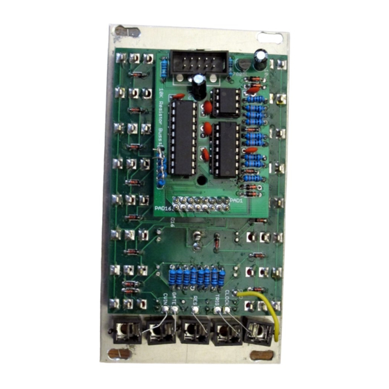
Header 2x8 Male Pin I buy 40 pin two row male header like this, and then cut it down. Header B. PCB Information To the right are images of the bottom and top of the bottom PCB and the top of the top PCB. C.Wiring Wiring is very simple. - Page 8 Here is a complete build using a home made resistor array.
- Page 9 Above is a close up of jack wiring. I used clipped resistor leads instead of wires to save on wire. Above is a close up of the connection between the two PCBs. Make sure you clip leads on the bottom side of the top PCB so they don't short against the 4051 that sits below the PCB. There are holes in the PCB to use an optional spacer to keep PCBs seperated.
Need help?
Do you have a question about the BMC58 and is the answer not in the manual?
Questions and answers