
Related Manuals for Barton Musical Circuits Chordizer


Summary of Contents for Barton Musical Circuits Chordizer
- Page 1 BMC052. Chordizer Last updated 8-27-2017 If you have any questions, or need help trouble shooting, please e-mail Michael@Bartonmusicalcircuits.com I Overview/Controls/Inputs/Outputs II Schematic III Construction A.Parts List B.The PCB C.Wiring D.Callibration...
- Page 2 I. Overview/Controls/Inputs/Outputs A. Overview – The goal of the Chordizer was to use a single voltage input and output a quantized chord of voltages when used with 1v/octave VCOs. A voltage is inputted through the IN jack and can be modulated by the AUX jack and it's associated attenuator. The voltage range for the input is 0 to 5V.
- Page 3 10.SAVE button – When pressed this will save the current offsets to the memory bank selected by the CHORD knob. 11.LOAD button – When pressed or when the LOAD input goes high, this will load offsets from the selected memory bank. Adjusting an OFFSET knob will override the loaded offset for that output.
- Page 4 II. Schematic.
- Page 5 On the previous page is the schematic for this module's printed circuit board. At the center is the 16F689 PIC microcontroller. The pinout for the chip is presented to the right. The Select toggle and Save button wirepads are connected directly to the pins of the PIC and pull down resistors from a 100K resistor bus.
- Page 6 III. Construction A.Parts List Semiconductors Name Quantity Notes 16F689 Should be provided with your PCB LM324 14 pin DIP package TL072 8 pin DIP package LM339 14 pin DIP package 4822 DAC 8 pin DIP package Switching diode 1N4148 or other small signal switching diode Schottky diode BAT46 or other schottky 78L05 Regulator...
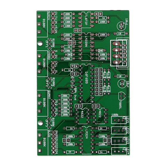
- Page 7 Knobs 20 pin DIP socket 14 pin DIP socket 8 pin DIP socket B. The PCB The PCB is 93x60mm. The mounting holes are spaced 51.1mm apart and pots are spaced 25.4mm apart. Below is an image of the PCB C.Wiring On the next page is a wiring diagram.
- Page 9 D. Calibration 1.Activate the Tune knob. 2.Adjust the trimpot for each channel until the output voltage of that channel is exactly 1V. 3.If your meter has low resolution, turn the SCALE knob fully clockwise to OCTAVES mode. 4.Input a 5V signal and turn the offset knobs to 12 O Clock. 5.Adjust the trimpots so that each channel is at 5V.
Need help?
Do you have a question about the Chordizer and is the answer not in the manual?
Questions and answers