Table of Contents
Advertisement
Quick Links
Auto-Seq Documentation
Written April 6th, 2014
I. Using The Module
A. What is Auto-Seq?
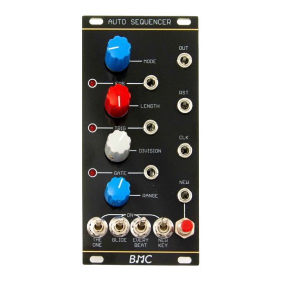
B. Controls/Inputs/Outputs
C. Sample Patches
II. Schematics
A.Chip Pinout
B.Inputs
1.Analog Inputs
2.Digital Inputs
C.Outputs
1.Analog Output
2.Digital Output
D.Power Supply
III. Construction
A.Parts List
B.Wiring/PCB Information
C.Calibration
Advertisement
Table of Contents

Related Manuals for Barton Musical Circuits Auto-Seq


Summary of Contents for Barton Musical Circuits Auto-Seq
- Page 1 Auto-Seq Documentation Written April 6th, 2014 I. Using The Module A. What is Auto-Seq? B. Controls/Inputs/Outputs C. Sample Patches II. Schematics A.Chip Pinout B.Inputs 1.Analog Inputs 2.Digital Inputs C.Outputs 1.Analog Output 2.Digital Output D.Power Supply III. Construction A.Parts List B.Wiring/PCB Information...
-
Page 2: Using The Module
B. Controls/Inputs/Outputs Controls 1. Mode - The Auto-Seq has a built in quantizer, this knob selects what musical mode it will quantize to. From least clockwise knob position to most clockwise, the modes are Major, Minor, Major Pentatonic, Minor Pentatonic, Fifths and Chromatic. - Page 3 For the first two sound samples, the diagram on the right shows the patch used. A clock is being input to the Auto-Seq. The Auto Seq's trigger and gate outs are being sent to Envelope Generators, which are then being sent to control the cutoff frequence of a VCF and the amplitude of a VCA.
-
Page 4: Analog Inputs
II. Schematics A. The Microchip On the right, we see the pinouts for the microcontroller. This chip is at the center of the design and all other schematics presented refer to the chip. Pins 19 - 16 are the analog inputs, these are all connected to knobs and read a variable voltage. -
Page 5: Digital Inputs
2. Digital Inputs. Below, we see the digital inputs. On the left of the diagram is a bussed 100K resistor array attached to ground and various other points. On the right we see some op-amps wired as comparators. These ensure that an input signal for the New, Reset or Clock input will be large enough to get a response from the microcontroller. -
Page 6: Digital Outputs
C. Outputs 1.Analog Output The analog output is pictured above. The 4921 is a digital-to-analog conversioni IC that is controlled by the serial data output of the microcontroller. We see soem pins on the 4921 are connected to the mmicrocontroller, and then it's output is fed into a pair of inverting amplifiers, one of which has a trimpot in it's feedback path. -
Page 7: D.power Supply
D.Power Supply Below, we see the power supply for the module. At the top are pads for two different kinds of connecters for modular synthesizer systems. The positive and negative rails are filtered by a 10 ohm resitor and 10uf capacitor, and then again at the pins of the TL074 with .1uf bypass capacitors. The +5V supply for the controls and the microcontroller is obtained with a 7805 voltage regulator. - Page 8 III. Construction A.Parts List Semiconductors Value Qty Notes 16F689 Pre programmed, should have come with your PCB TL074 14pin DIP, any quad op amp should work 7805 TO220 package 1n4148 MCP4921 DAC in 8 pin DIP format SD101C Or other small schottky 3mm size Resistors Value...
- Page 9 B.Wiring/PCB Information Above is the PCB. It is 86mm x 45mm. The mounting holes are spaced 82mm x 37mm and the pots are spaced 23mm apart. The wiring pads should be connected as follows (starting from the corner of the PCB nearest the panel): GN - Ground, connect the ground tab of one of the jacks +5 - +5V connect to the center tab of all the switches.
- Page 10 To wire the LEDs onto the board, just follow this sequence: C. Calibration 1.Before powering up, turn all the knobs completely clockwise, then turn the power supply on. The module will now be in calibration mode. 2.Use a voltage meter to read the CV output. 3.Adjust the trimpot until the CV output is exactly 6V.
Need help?
Do you have a question about the Auto-Seq and is the answer not in the manual?
Questions and answers