Table of Contents
Advertisement
Quick Links
Operation
Reactor®
Reactor® 3 3 3 Proportioning
Reactor®
Electric, heated,
heated, plural
plural component
Electric,
Electric,
heated,
plural
coatings.
coatings.
coatings. For
For
For indoor
indoor
indoor use
(classified)
(classified) locations.
(classified)
locations.
locations. Only
Important
Important Safety
Important
Safety Instructions
Safety
Read all warnings and instructions in this manual and in
related manuals before using the equipment. Save these
instructions.
See page 4 for model information
including maximum working
pressure.
Proportioning Systems
Proportioning
component proportioner
proportioner for
component
proportioner
use
use only.
only. Not
only.
Not
Not approved
approved
approved for
Only use
Only
use with
use
with Reactor
with
Reactor 3 3 3 heated
Reactor
Instructions
Instructions
PROVEN QUALITY. LEADING TECHNOLOGY.
Systems
Systems
for spraying
spraying polyurethane
polyurethane foam
for
spraying
polyurethane
for
for use
use in in in explosive
use
explosive atmospheres
explosive
heated hoses.
heated
hoses. For
hoses.
For professional
For
professional use
professional
3A8500A
foam and
and polyurea
polyurea
foam
and
polyurea
atmospheres or or or hazardous
atmospheres
hazardous
hazardous
use only.
use
only.
only.
EN
Advertisement
Table of Contents

Related Manuals for Graco Reactor 3 E-20 Elite


Summary of Contents for Graco Reactor 3 E-20 Elite
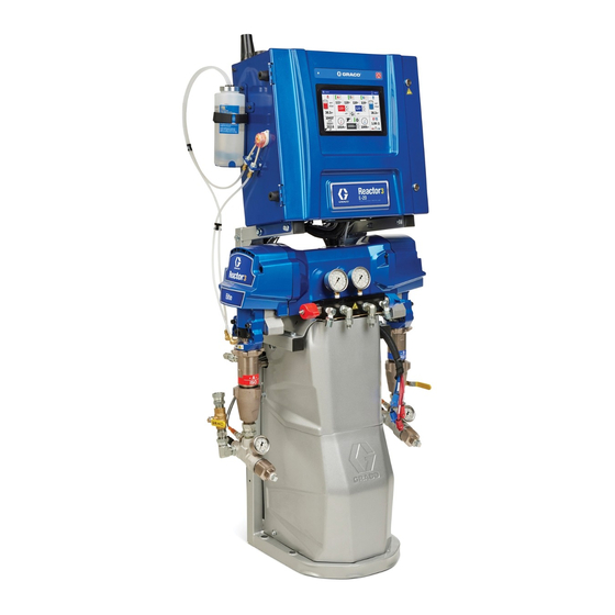
- Page 1 Operation Reactor® Reactor® Reactor® 3 3 3 Proportioning Proportioning Proportioning Systems Systems Systems 3A8500A Electric, heated, heated, plural plural component component proportioner proportioner for for spraying spraying polyurethane polyurethane foam foam and and polyurea polyurea Electric, Electric, heated, plural component proportioner spraying polyurethane...
-
Page 2: Table Of Contents
Tools Required for Setup ......23 General Equipment Guidelines ....23 Notes ............60 Connect Power ........24 Graco Extended Warranty for Reactor® Install Cell Module ........25 Components ........61 Supply Wet Cups With Throat Seal Liquid (TSL®)....... 26 Connect Heated Hose to Proportioner ....... -
Page 3: Supplied Manuals
Supplied Manuals Supplied Manuals Manuals Supplied Supplied Manuals The following manuals are shipped with the Reactor. Refer to these manuals for detailed equipment information. Manuals are also available at www.graco.com. Description Description Description Manual Manual Manual 3A8500 Reactor Proportioner Operation... -
Page 4: Models
Models Models Models Models Reactor Reactor Reactor E E E - - - 20 20 and and E E E - - - 30 Model Model Model E E E - - - 20 20 Elite Elite Elite 10 10 kW E E E - - - 30 30 Elite Elite 15... - Page 5 Models Reactor E E E - - - XP1 XP1 and and E E E - - - XP2 Reactor Reactor Model E E E - - - XP1 XP1 Elite Elite E E E - - - XP2 XP2 Elite Elite Model Model...
-
Page 6: Approvals
Approvals Accessories Accessories Accessories Approvals Approvals Approvals Description Intertek approvals apply to proportioners Description Description without hoses. Number Number Number 20A677 Engine CAN Kit Proportioner Proportioner Approvals: Proportioner Approvals: Approvals: 20A676 Light Tower Kit 24M174 Drum Level Sticks 18E175 Fluid Temperature Sensor Kit for Independent Hose Control 24N365 RTD Test Cables (to aide resistance... -
Page 7: Warnings
Warnings Warnings Warnings Warnings The following warnings are for the setup, use, grounding, maintenance, and repair of this equipment. The exclamation point symbol alerts you to a general warning and the hazard symbols refer to procedure-specific risks. When these symbols appear in the body of this manual or on warning labels, refer back to these Warnings. - Page 8 Warnings WARNING WARNING WARNING SKIN INJECTION INJECTION HAZARD HAZARD SKIN SKIN INJECTION HAZARD High-pressure fluid from gun, hose leaks, or ruptured components will pierce skin. This may look like just a cut, but it is a serious injury that can result in amputation. Get immediate immediate surgical immediate...
- Page 9 Warnings WARNING WARNING WARNING THERMAL EXPANSION EXPANSION HAZARD HAZARD THERMAL THERMAL EXPANSION HAZARD Fluids subjected to heat in confined spaces, including hoses, can create a rapid rise in pressure due to the thermal expansion. Over-pressurization can result in equipment rupture and serious injury. •...
- Page 10 Warnings WARNING WARNING WARNING EQUIPMENT MISUSE MISUSE HAZARD HAZARD EQUIPMENT EQUIPMENT MISUSE HAZARD Misuse can cause death or serious injury. • Do not operate the unit when fatigued or under the influence of drugs or alcohol. • Do not exceed the maximum working pressure or temperature rating of the lowest Technical Specifications Specifications in all equipment manuals.
-
Page 11: Important Isocyanate Information
Important Isocyanate Information Important Important Important Isocyanate Isocyanate Information Isocyanate Information Information Isocyanates (ISO) are catalysts used in two component materials. Isocyanate Conditions Conditions Isocyanate Isocyanate Conditions Spraying or dispensing fluids that contain isocyanates creates potentially harmful mists, vapors, and atomized particulates. •... - Page 12 Important Isocyanate Information Material Material Material Self Self - - - Ignition Self Ignition Ignition Moisture Moisture Sensitivity Moisture Sensitivity Sensitivity of of of Isocyanates Isocyanates Isocyanates Exposure to moisture (such as humidity) will cause ISO to partially cure, forming small, hard, abrasive crystals that become suspended in the fluid.
-
Page 13: Typical Installation
Typical Installation Typical Installation Installation Typical Typical Installation Typical Typical Typical Installation Installation Installation without without without circulation circulation circulation Figure 1 Reactor H � Agitator Air Supply Line Bleed Lines Proportioner B *� J � P � Heated Hose Bundle Fluid Supply Lines Gun Fluid Manifold D �... -
Page 14: Typical Installation Without
Typical Installation Typical Typical Typical Installation Installation with Installation with with system system fluid system fluid manifold fluid manifold manifold to to to drum drum drum circulation circulation circulation Figure 2 Reactor Proportioner H � P � Agitator Air Supply Line Gun Fluid Manifold B* �... -
Page 15: Fluid Manifold To Drum Circulation
Typical Installation Typical Typical Typical Installation Installation with Installation with gun with gun fluid fluid manifold fluid manifold to to to drum manifold drum circulation drum circulation circulation Figure 3 Reactor Proportioner H � Agitator Air Supply Line Bleed Lines B* �... -
Page 16: Component Identification
Component Identification Component Component Component Identification Identification Identification Proportioner Proportioner Proportioner 3A8500A... - Page 17 Component Identification ISO Side Pressure Relief Outlet RES Side Pressure Relief Outlet ISO Side Inlet Pressure Gauge RES Side Inlet Pressure Gauge Advanced Display Module (ADM) Electrical Cord Strain Relief Electric Motor ISO Side Inlet Fitting RES Side Inlet Fitting Fluid Heaters ISO Side Pressure Gauge RES Side Pressure Gauge...
-
Page 18: Electrical Enclosure
Component Identification Electrical Enclosure Enclosure Electrical Electrical Enclosure AAP * Temperature Control Module (TCM) Cellular Antenna Motor Control Module (MCM) AAR * GPS Antenna ADM LED Status Lights Wiring Terminal Blocks Reactor Connect Module Cable 24V Power Supply Connection Surge Protector ADM USB Port Transformer Breaker ADM CAN Cable Connection... -
Page 19: (Tcm)
Component Identification Temperature Control Control Module Module Temperature Temperature Control Module (TCM) (TCM) (TCM) ti36983b Description Ref. Description Description Ref. Ref. Main Power Input Heater Overtemperature Inputs CAN Communications Connections A/B Inlet Temperatures and 24 VDC Power Supply Input A Heater Temperature Input B Heater Temperature Input A/B Hose Temperature Inputs A/B Heater Power Outputs... -
Page 20: Motor Control Module (Mcm)
Component Identification Motor Control Control Module Module (MCM) (MCM) Motor Motor Control Module (MCM) ti36982b Description Description Description Description Description Description Ref. Ref. Ref. Ref. Ref. Ref. Motor Fan CAN Communication Connections ISO Lube Pump Output A-side Pump Outlet Pressure Main Power Input Digital Inputs/Outputs B-side Pump Outlet Pressure... -
Page 21: Installation
Installation Installation Installation Installation 2. Remove the enclosure pivot arm screws (ES). 3. Lift the electrical enclosure (EE). Ensure the TSL bottle remains upright as you lift the Location Location Location electrical enclosure. For ease of operation and maintenance, ensure there is adequate lighting in the area the Reactor is installed for visibility and safety. -
Page 22: Mount The System
Installation Mount the the System System Mount Mount System 5. Insert and tighten the TSL bottle mounting bracket screws to secure the bracket in the upright position. To prevent serious injury due to the system tipping over, ensure that the Reactor is properly secured to the wall. -
Page 23: Setup
Setup Setup Setup Setup General Equipment Equipment Guidelines Guidelines General General Equipment Guidelines NOTICE NOTICE NOTICE Grounding Grounding Grounding Failure to properly size the generator may result in damage. To avoid damage to the equipment, follow the guidelines listed below. •... -
Page 24: Connect Power
Setup Connect Connect Connect Power Power Power All electrical wiring must be done by a qualified electrician and comply with all local codes and regulations. 1. Turn the main power switch (MP) OFF. 2. Open the electrical enclosure door. NOTE: The terminal jumpers are located NOTE: NOTE: inside the electrical enclosure door. -
Page 25: Install Cell Module
Setup Install Cell Cell Module Module Install Install Cell Module 5. Attach the cellular antenna cable (ZE) to the cellular module. Tighten by hand. NOTE: NOTE: Installation of the cell module is required NOTE: 6. Attach the GPS antenna cable (ZD) to the to use the Reactor Connect app. -
Page 26: Liquid (Tsl®)
NOTICE NOTICE NOTICE pre-filled bottles from Graco, use a marker to draw a line at the top of the fluid line as it was To avoid damage to the hose, only connect shipped. Replace TSL if the fluid develops a Reactor 3 heated hoses to your Reactor gel-like consistency. -
Page 27: Startup
Startup Startup Startup Startup 4. Use A and B Drum Level Sticks (24M174) to measure the material level in each drum. If desired, the level can be entered and tracked with the ADM. 5. Check the generator fuel level. To prevent serious injury, only operate Reactor with all covers and shrouds in place. - Page 28 Startup 11. Turn on the air compressor, air dryer, and breathing air (if applicable). Cross-contamination can result in cured material in fluid lines which could cause serious injury or damage equipment. To prevent cross-contamination: • Never interchange component A and component B wetted parts.
- Page 29 Startup pump: see your pump manual, pump: pump: Related Manuals, page 3 13. Preheat the system: NOTE: NOTE: NOTE: The hose calibration must Thermal expansion can cause be completed before turning on the overpressurization, resulting in hose heat for the first time. See equipment rupture and serious injury, Calibrate the Heated Hose, page including fluid injection.
-
Page 30: Operation
Operation Operation Operation Operation Pressure Pressure Pressure Relief Relief Procedure Relief Procedure Procedure 6. Close the gun fluid inlet valves A and B. Follow the Pressure Relief Procedure whenever you see this symbol. The Fusion AP gun is shown. 7. Shut off the transfer pumps and agitator, if used. -
Page 31: Jog Mode
Operation Jog Mode Mode Mode 5. Tap to stop the motor. Jog mode has two purposes: Jog the the Transfer Transfer Pumps Pumps Separately Separately Transfer Pumps Separately • To speed fluid heating during circulation Pneumatic Pneumatic Pneumatic Transfer Transfer Transfer Pumps: Pumps: Manually turn Pumps:... -
Page 32: Purge Air Procedure
Operation Purge Air Air Procedure Procedure Purge Purge Procedure 8. Pump one gallon (3.8 L) of material through the system. 9. Set the pressure relief/spray valves (SA, SB) to spray NOTE: NOTE: NOTE: Perform this procedure any time air is introduced into the system. -
Page 33: Flush The Equipment
Operation Flush the the Equipment Equipment Flush Flush Equipment 5. Set the pressure relief/spray valves (SA, SB) to spray To help prevent fire and explosion: • Flush equipment only in a well-ventilated area. • Do not spray flammable fluids. 6. Hold the gun fluid manifold over two •... -
Page 34: Fluid Circulation
Operation Fluid Circulation Circulation Fluid Fluid Circulation Circulation Circulation Circulation Through Through Reactor Through Reactor Reactor 4. Tap +/- to set the temperature targets NOTICE NOTICE NOTICE for ISO and RES To prevent equipment damage, do not circulate fluid containing a blowing agent without consulting with your material supplier regarding fluid temperature limits. - Page 35 Operation Circulation Circulation Circulation Through Through Through Gun Gun Manifold Manifold Manifold 3. Follow Startup, page 4. Set temperature targets for ISO NOTICE NOTICE NOTICE To prevent equipment damage, do not circulate fluid containing a blowing agent and RES without consulting with your material supplier on the ADM screen.
-
Page 36: Calibration
Operation Calibration Calibration Calibration Calibrate Calibrate the Calibrate the Transfer Transfer Pumps Transfer Pumps Pumps After installing a new electric transfer pump, Calibrate Calibrate Calibrate the the Heated Heated Heated Hose Hose Hose you must calibrate the transfer pump motor. NOTICE NOTICE NOTICE... -
Page 37: Spray
Operation Spray Spray Spray 6. Open the fluid inlet valve located at each pump inlet. 1. Engage the gun piston safety lock and close gun fluid inlet valves A and B. Fusion Fusion Fusion Probler Probler Probler Pump Mode Mode button 7. - Page 38 Operation 12. Open the A and B gun fluid valves. 14. Pull the gun trigger to test spray onto cardboard. If necessary, adjust pressure and temperature to get desired results. Spray Adjustments Adjustments Spray Spray Adjustments Flow rate, atomization, and amount of overspray are affected by four variables: Fusion Fusion...
-
Page 39: Shutdown
Operation Shutdown Shutdown Shutdown 7. Turn off the air compressor, air dryer, and breathing air. NOTICE NOTICE NOTICE Proper system Setup, Startup, and Shutdown procedures are critical to electrical equipment reliability. The following procedures ensure steady voltage. Failure to follow these procedures will cause voltage fluctuations that can damage electrical equipment. -
Page 40: Advance Display Module (Adm)
Advance Display Module (ADM) Advance Display Display Module Module (ADM) (ADM) Advance Advance Display Module (ADM) Menu Menu Menu Bar Navigation The menu bar is located at the top of each screen of the ADM. The menu bar contains the Navigation Navigation menu (1), current screen (2), system notifications (3), and time (4). -
Page 41: Home Screen
Advance Display Module (ADM) Home Home Home Screen Screen Screen A A A and and B B B side side Supply side Supply Control Supply Control Panels Control Panels Panels The A and B Supply Control panels display the Use the Home screen to control the Reactor remaining material supply for A and B side system operation functions. - Page 42 Advance Display Module (ADM) Cycle Cycle Cycle Count Count Count Panel Panel Panel Proportioner Proportioner Control Proportioner Control Panel Control Panel Panel The Cycle Count panel contains information This Proportioner Control panel contains regarding pump cycles and the equivalent controls for operation of the proportioner pump. amount of material.
-
Page 43: Diagnostic Screen
Icon Name Description Icon Icon Name Name Description Description Help Tap to display a QR code with a link to help.graco.com for error help.graco.com help.graco.com and troubleshooting information. 3A8500A... -
Page 44: Setup Screens
Advance Display Module (ADM) Setup Setup Setup Screens Screens Screens Heat Heat Heat Use the Heat screen to calibrate hose heat and Use the Setup screens screens to edit settings set the hose control mode. for the Reactor system. To calibrate the system, see the Pressure/Flow Pressure/Flow Pressure/Flow... - Page 45 Advance Display Module (ADM) System System System Enable Power Tap the checkbox to enable/disable Management power management. Tap the number Use the System screen to set system settings. to adjust the primary heater power limit. Description Setting Setting Setting Description Description Power management allows users to limit the primary heater wattage to...
-
Page 46: Advanced Screens
Tap the checkbox to enable/disable After resetting your Reactor key, all operators Chemical Alarms Low Chemical Alarms. Tap the using the Graco Reactor Connect app must number value to adjust the alarm reconnect to the Reactor. threshold. For security of wireless control, change the... - Page 47 Advance Display Module (ADM) Display Display Display Software Software Software Use the Display screen to set the language, The Software screen displays the system part date format, current date, time, setup screens number, system serial number, software part password, screen saver delay, temperature number, and software version.
-
Page 48: Maintenance
Grease Circulation Valves Wet Cup Clean the grease circulation valves weekly. Check the wet cup daily. Keep it 3/4 full with Graco Throat Seal Liquid (TSL ) or compatible ® solvent. Do not over tighten packing nut/wet Desicant Desicant Dryer... -
Page 49: Flush Inlet Strainer Screen
Maintenance Flush Inlet Inlet Strainer Strainer Screen Screen Flush Flush Inlet Strainer Screen 5. After the fluid has drained, remove the cap (ZC) and screen (ZA) from the strainer manifold. Thoroughly flush the screen with compatible solvent and shake it dry. Inspect the screen. -
Page 50: Pump Lubrication System
No priming is Check the condition of the ISO pump lubricant required. Graco TSL daily. Change the lubricant if it becomes a gel, its color darkens, or it becomes diluted with isocyanate. Gel formation is due to moisture absorption by the pump lubricant. -
Page 51: Troubleshooting
Errors Troubleshoot Troubleshoot Errors sent directly to online troubleshooting for the active error code. Otherwise, go to help.graco.com and search for the active help.graco.com help.graco.com When an error occurs the error information error. screen displays the active error code and description. -
Page 52: Led Status Descriptions
Troubleshooting LED Status Status Descriptions Status Descriptions Descriptions The following tables describe the meaning of LED statuses for the TCM, MCM, ADM, and System. Table Table Table 1 1 1 TCM TCM Module Module Module LED LED Status Status Descriptions Status Descriptions Descriptions... -
Page 53: Performance Charts
Performance Charts Performance Performance Performance Charts Charts Charts Use these charts to help identify the proportioner that will work most efficiently with each mix chamber. Flow rates are based on a material viscosity of 60 cps. NOTICE NOTICE NOTICE To prevent system damage, do not pressurize the system above the line for the gun tip size being used. - Page 54 Performance Charts Heater Heater Heater Performance Performance Performance Chart Chart Chart (60) (54.4) (48.9) (43.3) (37.8) (32.2) (26.7) a T in Power (7kW) degrees F (21.1) (degrees C) Power (10kW) Power (15kW) (15.6) (10) (4.4) (-1.1) (-6.7) (-12) (-17.8) (1.9) (3.8) (5.7) (7.6)
-
Page 55: Technical Specifications
Technical Specifications Technical Technical Technical Specifications Specifications Specifications Reactor E E E - - - 20 Reactor Reactor Reactor 3 3 3 Proportioning Proportioning Systems, Systems, E E E - - - 20 Reactor Reactor Proportioning Systems, U.S. U.S. U.S. Metric Metric Metric... - Page 56 Technical Specifications Reactor Reactor Reactor E E E - - - 30 Reactor Reactor 3 3 3 Proportioning Reactor Proportioning Systems, Proportioning Systems, Systems, E E E - - - 30 U.S. Metric Metric Metric U.S. U.S. Maximum Fluid Working Pressure 2000 psi 140 bar, 14 MPa Maximum Fluid Temperature...
- Page 57 Technical Specifications Reactor E E E - - - XP1 Reactor Reactor Reactor 3 3 3 Proportioning Proportioning Systems, Systems, E E E - - - XP1 Reactor Reactor Proportioning Systems, U.S. Metric U.S. U.S. Metric Metric 3000 psi Maximum Fluid Working Pressure 207 bar, 20.7 MPa Maximum Fluid Temperature 180 °F...
- Page 58 Technical Specifications Reactor Reactor Reactor E E E - - - XP2 Reactor Reactor 3 3 3 Proportioning Reactor Proportioning Systems, Proportioning Systems, Systems, E E E - - - XP2 U.S. Metric Metric Metric U.S. U.S. Maximum Fluid Working Pressure 3500 psi 241 bar, 24.1 MPa Maximum Fluid Temperature...
-
Page 59: California Proposition 65
California Proposition 65 California California California Proposition Proposition Proposition 65 CALIFORNIA CALIFORNIA RESIDENTS CALIFORNIA RESIDENTS RESIDENTS WARNING: WARNING: WARNING: Cancer and reproductive harm — www.P65warnings.ca.gov. 3A8500A... -
Page 60: Notes
Notes Notes Notes Notes 3A8500A... -
Page 61: Components
With the exception of any special, extended, or limited warranty published by Graco, Graco will, for a period of twelve months from the date of sale, repair or replace any part of the equipment determined by Graco to be defective. This warranty applies only when the equipment is installed, operated and maintained in accordance with Graco’s written recommendations. - Page 62 For the latest information about Graco products, visit www.graco.com. For patent information, see www.graco.com/patents. To place place place an an order, order, contact your Graco Distributor or call to identify the nearest distributor. order, Phone: 612-623-6921 or or or Toll Toll Free: Free: 1-800-328-0211 Fax: Fax: 612-378-3505...
Need help?
Do you have a question about the Reactor 3 E-20 Elite and is the answer not in the manual?
Questions and answers