
Subscribe to Our Youtube Channel
Related Manuals for Ilsintech Multipack-F


Summary of Contents for Ilsintech Multipack-F
- Page 1 All-in-one Preparation kit for the Optical Fiber Field Termination Read this service manual carefully before using Multipack-F. Multipack-F USER MANUAL WWW.ILSINTECH.COM...
- Page 2 Users need to understand that this device (A Class) has (Broadcasting and obtained EMI (Electromagnetic compatibility) and been communication device, designed to be used in places other than home. commercial use) Telephone +82 42 671 5609~11 Homepage www.ilsintech.com E-mail sales@ilsintech.com...
-
Page 3: Table Of Contents
NOTES TO USERS SPECIFICATIONS AND COMPONENTS Specifications In the package III. HOW TO USE Power Supply Battery IV. FEATURES Body Multipack-F Auto Stripper Multipack-F Alcohol dispenser Multipack-F Cleaver Multipack-F Sleeve Heater Multipack-F Optical Power Module OPERATION Function buttons Multipack-F Activation... - Page 4 Inserting optical fiber into the splice sleeve tube. Stripping Procedure Cleaning Procedure Cleaving Optical Fiber Placing a sleeve tube into the sleeve heater Heating Sleeve Tube VI. MAINTENANCE Auto Stripper maintenance Cleaver maintenance Sleeve Heater maintenance Optical Power Modules maintenance VII.
- Page 5 Sleeve Heater Mode Setting Stripping Mode Setting Optical Power Meter VIII. MENU OPERATION Going to Submenu Going Up to Main Menu Changing Modes or Preset Values Example for Mode Alteration Example for Preset Value Alteration IX. WARRANTY PERIOD AND CONTACT Warranty Period and Limit of Responsibility Before sending the equipment For more effective maintenance and repair...
-
Page 7: Notes To Users
Therefore, use Multipack-F only after thoroughly understood this user manual. Keep this user manual along with equipment at all times. ILSINTECH Co., Ltd is not liable for any personal injury, physical loss and damage to equipment caused by inappropriate use or unauthorized modification of the Multipack-F. - Page 8 Always connect to 3-core AC power cord. Do not use 2-core AC power cord, cable and plug. Do not touch AC plug, AC power cord or Multipack-F with a wet hand. It could result in electric shock. Do not disassemble AC adapter, battery or the Multipack-F. Transforming or modification of Multipack-F unit could cause fire, electric shock or injury.
- Page 9 Do not make a short circuit of the terminals of the charger(MPF-B). Excessive current may cause personal injury and equipment damage. Do not use Multipack-F in an environment in which flammable liquids or hazardous gas exists. The electric arc of Multipack-F may cause fire or explosion.
- Page 10 Do not place Multipack-F in an uneven surface. The unit may fall, causing personal injury or equipment damage. Do not apply shock on Multipack-F, since it is a precision machine. When moving or storing Multipack-F, use the carrying case which is designed for the equipment. The carrying case protects the equipment against humidity, vibration and shocks and prevents damages during its storage and moving.
-
Page 11: Specifications And Components
Specifications and Components 1. Specifications Subject Description Applicable type of 0.25mm, 0.9mm, 2.0mm, 3.0mm, 4.0mm, Indoor cable fibers Applicable type of SC, FC, ST, LC connector Fiber count Single fiber Applicable fiber Cladding diameter: 125㎛, Coating diameter: 250, 900㎛ dimensions Fiber setting and 8.0mm cleaved length... -
Page 12: In The Package
2. In the package Holder Heater Block Tool Box Allen wrench Cooling Tray Tweezer Brush Carrying Case Multipack-F Work Belt Charger Set... - Page 13 Standard Package Option Package Category Model Q’ty Category Model Multipack-F Cleaver Blade BI-05 Battery Charger MPF-B Battery Charger MPF-B AC Adapter LYD1805000 Sleeving Clamp SC-01 Cooling Tray CT-01 Manual Stripper MS-01 80S/S178 250,900, IN, 3.0F, Allen wrench 1.5/2.0/2.5 1set Compatible...
- Page 14 1) Preparation for the Operation Fiber types 0.25 mm 0.9 mm Basic sleeve Fiber Length: 40mm Length: 28mm protection sleeve Length: 20mm Length: 25mm Micro sleeve Length: 34mm Length: 45mm Fiber holder Fiber holder [FTTH] [Standard] (250/900) (SOC(Splice-On Connector)) Cleave length : 8mm (Fixed) Cleave length : 8mm (Fixed) Fiber holder...
-
Page 15: How To Use
Use only the charger and AC adaptor provided with the equipment. The battery of Multipack-F (MPF-B) has a protection circuit and function to prevent over discharge, overcharge and overload. The power is cut off when protective function is... - Page 16 Checking remaining battery capacity The remaining capacity of a battery is indicated at the top right on the screen when Multipack-F is in use. Remaining battery level Remaining battery level display Remaining battery (Monitor) (LED) percentage 5 bars 5 LED...
-
Page 17: Battery
2. Battery Battery installation Use lock button to Install and remove the battery. Battery Lock button Battery... -
Page 18: Features
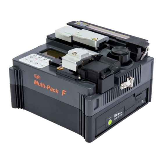
IV. Features Multipack-F is compact, light and convenient. It is recommended to carefully read the user manual before operation to understand the entire functions of Multipack-F. 1. Body... - Page 19 Sleeve Heater Stripper Cleaner Cleaver LCD Monitor Control Auto Chip Collector (Option) Optical Power Module...
-
Page 20: Multipack-F Auto Stripper
2. Multipack-F Auto Stripper 1) Features Multipack-F automatic fiber stripper automatically carries out an accurate stripping of the coating of single fibers. Featuring excellent tensile force of fiber, the automatic stripper strips up to 27mm in length without damaging the surface of fiber. Read the user manual thoroughly to maintain the best performance of the unit. - Page 21 3) Configuration and the parts Blade Slide Cover Heater Cover Heater Slide Base < Front View > < Control Panel > Monitor POWER ON/OFF Stripper Button...
-
Page 22: Multipack-F Alcohol Dispenser
3. Multipack-F Alcohol dispenser 1) Features The alcohol dispenser in the Multipack-F has a limited capacity; the pump can be removed and refilled with cleaning fluid. When refill the cleaner, use ethyl alcohol (96%). 2) Specifications Dispensing method Air-pump Capacity of the alcohol dispenser /... -
Page 23: Multipack-F Cleaver
4. Multipack-F Cleaver 1) Features The cleaver is designed to cleave the fiber at a 90 degree angle. For the best result, following requirements should be satisfied. The coating of fiber shall be thoroughly stripped. Optical fiber installed on holder groove should be straightened all the way The state of cutting blade on the cutting part and the height of blades should be accurate. -
Page 24: Multipack-F Sleeve Heater
5. Multipack-F Sleeve Heater 1) Features The sleeve heater is designed to strengthen the fiber spliced. The following conditions must be satisfied to ensure maximum reinforcement. The fiber splice point must be visually perfect after splicing The optical fiber whose sleeve tube is inserted on sleeve heater should be correct in its alignment and installation. - Page 25 3) Configuration and the parts Heater Cover-L Heater Cover-R Heater Window < Control Panel > < Front >...
-
Page 26: Multipack-F Optical Power Module
6. Multipack-F Optical Power Module 1) Features The optical power module of Multipack-F is consisted of the optical power meter to measure optical power and the visual fault locator to check the disconnection of line. For exact measurement and utilization, the following conditions should be satisfied.. - Page 27 2) Specifications (1) Multipack-F optical power meter Technical Specifications Power range 5 to -50 dBm Measurable wavelengths 1310, 1490, 1550 nm Calibrated wavelengths 1310, 1550 nm Power uncertainty ±5% Resolution 0.01 dBm Tone detection 270, 330, 1k, 2k Hz Tone detecting range...
- Page 28 (2) Multipack-F Visual fault locator Technical Specifications Laser source Class 2 laser diode 650nm ± 20nm Laser wavelength Fiber compatibility SM and MM Output power <1mW into single mode fiber Universal adapter for connectors with Output port 2.5mm ferrules Distance range <4km...
- Page 29 3) Configuration and the parts Optical Power Modules Power meter Universal adapter Cover Photo diode Ferrule...
-
Page 30: Operation
V. Operation 1. Function buttons Turns the power On/Off. The power is turned On/Off with beep sound upon pressing this button for about 1 second. Supplies power to the stripper heater. Toggles On/Off when pressed. LED is lit upon pressing this button and optical fiber can perform stripping after the stripper heater reaches the targeted temperature. -
Page 31: Multipack-F Activation
2. Multipack-F Activation Press and hold power button for 1 second. Check the red light turns on. 3. Inserting optical fiber into the splice sleeve tube. Insert optical fiber into the splice sleeve tube based on the assembling direction before stripping. -
Page 32: Stripping Procedure
4. Stripping Procedure ① Preheat the heater by operating the stripping part control as shown in the picture. Open thermal heater cover and slide cover for preparation. < Control Panel > < Automatic Fiber Stripper > ② Place fiber into the holder as shown below pictures. The minimum stripping length should be longer than 18mm. - Page 33 ④ Upon closing the heater cover, the optical fiber is heated for the predetermined time period and then stripping is performed with the slider’s automatic move. < Φ250 type > < Φ900 type > < Φ2.0~3.0 type > ⑤ When stripping is completed, open the slide cover and pick up the holder with the stripped fiber.
-
Page 34: Cleaning Procedure
Alcohol dispenser is attached to Multipack-F body with a magnet so pull it up all the way and completely separate it from Multipack-F body to refill the cleaner. ③ Use ethyl alcohol (96%) as the designated cleaner. -
Page 35: Cleaving Optical Fiber
6. Cleaving Optical Fiber ① Open the cover and set the holder on which the stripped optical fiber is installed at the position for cutting the body. On doing this job, make the holder close to one side of holder base to make the optical fiber form a right angle to the blade. <... -
Page 36: Placing A Sleeve Tube Into The Sleeve Heater
④ Remove the cleaved optical fiber and the holder. Be careful not to contaminate them with dust or foreign substance upon removal. Chips of cleaved optical fiber are automatically collected in the chip box. <Φ250 광섬유> <Φ900 광섬유> <SOC> 7. Placing a sleeve tube into the sleeve heater Φ250, Φ900 type : Place sleeve tube in the middle of sleeve heater and fix it by pushing it down. -
Page 37: Heating Sleeve Tube
8. Heating Sleeve Tube ① Place the fiber which has been inserted into sleeve tube into heater. ② Place optical fiber – in which sleeve tube is put – on the sleeve heater. To make heater cover automatically closed when putting on sleeve heater, put the optical fiber while being hung upon the heater lever. - Page 38 Operation Procedure (Heating Sleeve) ① As shown in the picture below, apply power to the control panel and open the cover of the heater to prepare. < Control Panel > < Heating Sleeve > ② Set the sleeve tube to the area of arc-fused fiber that needs to be reinforced and place the fiber inside the heater.
- Page 39 ③ Activate the heater after placing the fiber. Approximately in 30 seconds after operation of sleeve heater, sleeve tube is cooled. < Control Panel > <Φ250 type > <Φ900 type > <SOC type > ④ Open the cover when cooling is completed and take out the reinforced fiber. <Φ250 type >...
-
Page 40: Maintenance
VI. Maintenance 1. Auto Stripper maintenance ① Remove worn out blade by unscrewing fixed bolts as shown below picture, and move the slide part to the left hand side. ② Place new blade in the reverse manner of removing. (Two blades as a pair at top and bottom) For the perfect setting and fine stripping, there should be no cracks when the top and bottom blades make contact. -
Page 41: Cleaver Maintenance
2. Cleaver maintenance - 1 to 16 channel (cleave positions) is marked on a blade. - If a blade does not cut fiber properly, clean the edge and top and bottom rubber pads of the blade with a cotton swab wet in alcohol - (Do not use acetone or solvent to clean the rubber pads.) - If the life of the blade is almost over, fiber may not be cleaved clean. - Page 42 ③ Open the cover and push the slider forward. When the slider is fixed, loosen the set screw a little bit (about 2 turns) with a hexagon wrench. ④ Turn the number on markings of blade by one click counterclockwise with a cotton swab. Fixing: reverse order.
- Page 43 ③ Insert the wrench bolt into the cam pin and pull it with tweezers and detach the slider. ④ Be careful not to damage the blade. Assemble the part in the reverse manner. Tighten the set-screw firmly. 3) Adjustment of blade height ①...
-
Page 44: Sleeve Heater Maintenance
2) The Choice of Heater Block / Lever Block by fiber type < Heater Block-R assembly < Heater Block-R-C assembly – 250, 900, 2.0~ 4.0mm Indoor Cable> – SC/ FC/ ST/ LC Connector > ※ Multipack-F basic assembling: Heater Block-R-C assembly Multipack-F components: Heater Block-R assembly... -
Page 45: Optical Power Modules Maintenance
- Keep it clean and in a carry case when not using, which will increase the life of the equipment. 4. Optical Power Modules maintenance 1) Multipack-F Optical Power Meter ① Block foreign substances with metal cap on when not being used. - Page 46 2) Multipack-F Visual fault locator ① Stay metal cap locked to block foreign substances when not in use.
-
Page 47: Menu
VII. Menu 1. Main Menu Press MENU button on [Mode Menu], and it returns to [Main Menu]. HT MODE indicates sleeve heater mode. You can change mode on main menu. ST MODE indicates stripping mode. You can change mode on main menu. CW measures and displays tone frequency of current optical power. -
Page 48: Mode Menu
2. Mode Menu ① Press MENU button on [Main Menu], and it goes to the [Mode Menu]. You can enter each mode by moving the cursor with LEFT and RIGHT button. ② Press MENU button on [Mode Menu], and it returns to [Main Menu]. ③... -
Page 49: Stripping Mode (Str Mode Menu)
4. Stripping Mode (Str Mode Menu) ① Move the cursor to “Str Mode Menu” on [Mode Menu] and then press ENTER key, and you will enter [Stripping Mode Menu]. ② Move the cursor with LEFT and RIGHT button on [Stripping Mode Menu], and you can change preset values on each mode. -
Page 50: Checking Program Version (Program Ver)
6. Checking Program Version (Program Ver) ① Move the cursor to “Program Ver” on [Mode Menu] and then press ENTER key, and you will enter [Program Version]. ② You can see the current version of program. 7. Sleeve Heater Mode Setting ①... -
Page 51: Stripping Mode Setting
8. Stripping Mode Setting ① Move the cursor to [Stripping Mode Menu] with LEFT and RIGHT button and then press ENTER key, and you will enter [Heater Mode Setting]. ② Time determines the heating time for stripping (waiting time from closing the cover until stripping is completed). -
Page 52: Menu Operation
VIII. Menu Operation 1. Going to Submenu ① Press MENU button on [Main Menu], and it goes to [Mode Menu], the submenu. ② Move the cursor to a targeted mode menu on [Mode Menu] and then press ENTER key, and it goes to the submenu of [Mode Menu]. ③... -
Page 53: Example For Mode Alteration
4. Example for Mode Alteration (Wavelength alteration for optical power meter) ① Move the cursor to “1310nm” [wavelength] with LEFT and RIGHT button and then press ENTER key, and you will enter [wavelength setting]. ② Cursor starts flickering upon pressing ENTER key. ③... -
Page 54: Example For Preset Value Alteration
5. Example for Preset Value Alteration (Preset value alteration on sleeve heater mode) ① Locate the cursor at “175C” as in the figure below on Menu for Setting Heater Mode. ② Cursor starts flickering upon pressing ENTER key. ③ The preset value goes down to “174C” upon pressing LEFT button once. ④... -
Page 55: Warranty Period And Contact
IX. Warranty Period and Contact 1. Warranty Period and Limit of Responsibility If Multipack-F is broken within one year from delivery, it will be repaired by the manufacturer for free. However, the buyer will be charged for the repair regardless of the warranty period if the breakage or damage incurred due to. -
Page 56: For More Effective Maintenance And Repair
4. Transport Multipack-F is high-precision equipment. So it is required to protect it from moisture, vibratiom, shake or physical impact by transporting it after keeping in an exclusive carrier case. When requesting for repair service, please, make sure that the body with components is sent in an exclusive carrier case. -
Page 58: Products Warranty
This warranty card has to be presented when the product is repaired. Multipack-F is high precision equipment, so it is required to transport after keeping it in an exclusive carrier case to protect it from humidity, vibration and physical shock.
Need help?
Do you have a question about the Multipack-F and is the answer not in the manual?
Questions and answers