Table of Contents
Advertisement
Quick Links
Advertisement
Table of Contents

Related Manuals for Ilsintech SWIFT K33


Summary of Contents for Ilsintech SWIFT K33
- Page 2 USER MANUAL This device complies with Part �� of the FCC Rules. Operation is subject to the following two conditions: 1. This device may not cause harmful interference. �. This device must accept any interference received, including interference that may cause undesired operation.
-
Page 3: Table Of Contents
TABLE OF CONTENTS FOR YOUR SAFETY � Swift K�� sleeve-heater part �� Separation of connected optical fiber �� SPECIFICATIONS � Heating for protecting sleeve �� General specifications � Components � MAINTENANCE OF SPLICE QUALITY �� Cleaning and inspection before splice ��... - Page 4 TABLE OF CONTENTS ERROR MESSAGE �� Q & A �� Too dirty fiber �� Power �� Replace the optical fiber �� Splice �� �� Sleeve heater �� Too long fiber Fiber over angle �� The others �� Loss is higher ��...
-
Page 5: For Your Safety
FOR YOUR SAFETY KEEP THIS The Swift K�� is designed to UCLSWIFT Co., Ltd is not liable satisfy the user’s convenience USER MANUAL for any personal injury, for both outdoor and indoor any physical loss and damage use, allowing the operation WITH THE todevice caused by inappropriate easy and simple. - Page 6 FOR YOUR SAFETY WARNING to the equipment, it is important Connect the supplied AC power · DO NOT apply excessive shock thatregularly check the generator cord to the battery. Check to to the battery. before use. DO NOT excessively Please, turn off the Swift K�� ensure no dust or foreign sub- ·...
- Page 7 FOR YOUR SAFETY CAUTIONS belt before transporting. Trans- · Replace the electrodes as Technical aspects of Swift K�� porting the case with a damaged a pair. should be inspected by a quali- DO NOT touch the sleeve heater shoulder belt, it may cause the fied expert.
-
Page 8: Specifications
SPECIFICATION GENERAL SPECIFICATION Subject Description Fiber Alignment IPAAS Core Alignment Return Loss > ��dB (Typical) SM(G.���), MM(G.���), Applicable Splicing Time Typical � sec. (Quick Mode) DS(G.���), NZDS(G.���), Fibers SM(G.��� A�, A�/B�, B�), Storage of Splice The last ��,��� results to be SM(G.���E) Result stored in the internal memory. - Page 9 SPECIFICATION Storage Conditions Temperature: -��℃~��℃, Viewing method Two CMOS cameras and �.�-inch Humidity: �~��% and Display color LCD monitor with Electrostatic touch screen Operating Altitude: �~�,���m above sea level Power Supply ��� ~ ���V AC Condition Temperature: -��℃~��℃ Humidity: �~��%, Battery life with ���...
-
Page 10: Components
SPECIFICATION COMPONENTS Standard Items Description Model No. Quantity � Arc Fusion Splicer SWIFT K�� � Tool box Download from User Guide USB Cable � UCL Swift Website (uclswift.com) Sleeve Loader � Battery K����(�,���mAh) � Transporting Case Hard Case � AC Adapter �... - Page 11 SPECIFICATION Optional Items Description Model No. Battery K����(�,���mAh) Work Belt Cleaver Blade BI-�� SOC Connector SC, LC, FC, ST(refer to FTTx solution catalogue) Electrode EI-�� Optical Fiber Holder HS-���, HS-���, HS-�.�F, HS-IN, HS-SC/FC, HS-ILC, HS-ST, LS-��� (Loose tube) External Power DC ��V available for car cigar jack Sleeve S-���...
-
Page 12: Product Description
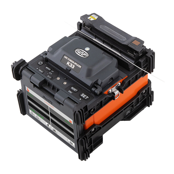
PRODUCT DESCRIPTION PART NAME OF SWIFT K�� Windshield Cover Sleeve Heater Wifi Card Slot DC OUT Data Sync Monitor Battery Lock Lever Remaining Battery �� (Touch Panel) Display Button / Display... -
Page 13: Function Buttons
PRODUCT DESCRIPTION Heater Cover H-Cnnector Cooling Tray Block Function Button HEAT To turn the power on/off-press To activate the sleeve heater To execute splicing command button for about �.� second. RESET To X/Y screen conversion To return to the initial screen, Press for about �... -
Page 14: Operation
OPERATION SUPPLYING POWER TO THE SWIFT K�� It is strongly recommended to use the AC adapter (F�-�) and battery (K����) provided with package. Using a battery other than provided may cause fumes, fire, and damage to the device, personal injury and death. Inserting the Battery Insert the battery into the battery groove until it clicks. - Page 15 OPERATION AC Cord DC Jack DC Cord AC/DC Adapter Make sure the voltage and frequency and connect Swift K�� can be charged during operation because the floating charging method is applied. The battery the DC cord of the AC/DC adapter to the DC jack of the can be also charged with ��V Cigar jack charger.
-
Page 16: How To Check Remaining Battery Capacity
OPERATION HOW TO CHECK It is strongly recommended REMAINING BATTERY that the battery must be charged as remaining capacity CAPACITY reaches to ��% (� bar). If not, there occurs the splice loss. Percentage Remains Remaining Battery Amount (Monitor) Remaining Battery Capacity Display (LED) �... -
Page 17: Turn On The Swift K
OPERATION TURN ON THE SWIFT K�� INSTALLING THE SLEEVE LOADER Press and hold for about �.� second without Get the sleeve loader installed as follows. opening the windshield cover. The initial screen is displayed as above after resetting all their initial functions. -
Page 18: Inserting The Fiber Into The Sleeve
OPERATION INSERTING THE FIBER OPTICAL FIBER INTO THE SLEEVE CLEANING AND STRIPPING Insert the fiber into the sleeve. Do stripping procedure on about �cm from the end of optical fiber by using sheath stripper. And wipe the optical fiber clean with soft cloth or cotton moistened with alcohol Use high quality ethyl-alcohol with higher than ��% purity. -
Page 19: Cleaving The Fiber
OPERATION CLEAVING LOAD THE FIBER THE FIBER TO SWIFT K�� � Install the optical fiber on cutter as shown in the figure � Open the windshield cover and optical fiber. below and check optical fiber’s state and cutting length. � Put optical fiber between V-Groove and electrode. �... -
Page 20: Splice
OPERATION SPLICE appears on the screen and the splice process stops. Though no error message appears on the screen, visual inspection on cross section is recommended as the process stops. � Optical fibers are arrayed core vs core after inspection. Deviation on clad axis and deviation measured on core axis can be displayed on screen. -
Page 21: Swift K
OPERATION SWIFT K�� SLEEVE-HEATER PART Sleeve heating part of K�� realizes reinforcement of Cable Diameter ���μm, ���μm, �.�mm ~ �.�mm single optical fiber subject to sealing splice. State of Sleeve Length �� ~ ��mm sealing splice on optical fiber should be appropriate. Optical fiber that sleeve tube is inserted to heater Sleeving Time �... - Page 22 OPERATION Optical Fiber � Choose the heater mode after the confirmation � After placing the optical fiber on the heater, press button of the length for the sleeve tube when placing a sleeve to start the heater. (Operation time: about �� seconds). tube on a heater.
-
Page 23: Separation Of Connected Optical Fiber
OPERATION SEPARATION OF HEATING FOR CONNECTED OPTICAL PROTECTIONG SLEEVE FIBER � Open the cover of sleeve heater. � Open the windshield cover. � Hold the optical fiber on the left and open the clamp on the left. � Open the optical fiber clamp on the right. �... -
Page 24: Maintenance Of Splice Quality
MAINTENANCE OF SPLICE QUALITY CLEANING AND INSPECTION BEFORE SPLICE V-Groove Cleaning When the inside of V-Groove is contaminated, splice quality may deteriorate. Thus, it is important to regularly inspect and frequently clean the V-Groove as follows. � Open the windbreak cover. �... - Page 25 MAINTENANCE OF SPLICE QUALITY Pusher Block Cleaning Cutter Cleaning Contaminations remaining on Pusher Block incur When cutter’s blade and fixing pad is contaminated, poor splice quality with influence on pusher cutting quality may deteriorate. Splice loss can be block location. Thus, it is important to frequently consequently increased.
-
Page 26: Regular Cleaning And Inspection
MAINTENANCE OF SPLICE QUALITY REGULAR CLEANING AND INSPECTION To keep sealer’s splice quality, regular inspection and cleaning is required. Object Lens Cleaning � Turn the power off before cleaning the object lens. � Separate the electrode. � Clean it using a soft cotton swab moistened with alcohol making a circle from the center as in the figure below. - Page 27 MAINTENANCE OF SPLICE QUALITY Cutter Blade Rotation When cutter fails to cut optical fiber properly, rotate the blade as follows. � Unscrew the right and the left � Rotate the blade one gauge only � Tighten the right and the left clamp clamp screw using �.�...
- Page 28 MAINTENANCE OF SPLICE QUALITY Electrode Replacement It is recommended to replace electrode after using �,��� times. If the actual number of arc discharge exceeds the replacing cycle, a message for electrode replacement is displayed on the screen. Without electrode replacement, splice loss increases and tensile force at splicing point weakens.
-
Page 29: Menu
MENU MENU MENU Ready State Main menu has � submenus. Press Ready State MENU READY touch the icon on the screen to load MENU main menu. The main menu screen is as above. You can select right and left by pressing DELETE : It deletes splice mode. - Page 30 MENU DELETE : It deletes heater mode. STABILIZE : It conducts electrode stabilizing. REPLACE : It selects and replaces a certain REPLACE : It explains how to replace electrode. heater mode within database. ELECTRODE CAUTION : It sets the number HEATER ELECTRODE ADD : It selects and adds a certain heater...
-
Page 31: Pop-Up Menu
MENU POP-UP MENU Popup menu of Swift K�� has been changed to a new form. Purpose of popup menu is to facilitate easy and quick access to splice mode and heater mode. User can access popup menu in various ways. Importing Pop-up Menu Splice Pop-Up Menu Heater Pop-Up Menu... - Page 32 MENU Splice Pop-Up Menu Adding Splice Menu Deleting Splice Mode � Import splice popup menu by pressing � Delete a splice mode by touching icon. SPLICE icon on screen of initial state. � Select a mode to be deleted. � Select an empty slot by pressing touching the touch screen.
- Page 33 MENU Heater Pop-Up Menu Adding Heater Menu Deleting Heater Mode � Import heater popup menu by pressing � Delete a heater mode by touching icon. HEATER icon on screen of Ready state. � Select a mode to be deleted. � Select an empty slot by pressing touching the touch screen.
-
Page 34: Splice
MENU SPLICE To import splice mode, press and select General splice mode : No. � ~ �� SPLICE icon by touch. It displays a screen to select User splice mode : No. �� ~ ��� splice mode as follows. The selecting screen The splice mode from No.�... - Page 35 MENU Outline of Splice Mode Splice Mode Description It is a mode for basic SM optical fiber. MFD of single mode optical fiber is about �~��um at ����nm wavelength. It is a mode for NZDS optical fiber. MFD of NZDS optical fiber is about �~��um at ����nm wavelength.
- Page 36 MENU � Click , then the splice modes � Select the splice mode, click � The selected splice mode is added the last SELECT stored in memory is displayed on the The selected splice mode is added the blank mode. screen.
- Page 37 MENU Replace � Select the splice mode to be replace, � The selected splice mode is added the last � Click , then the splice modes REPLACE click blank mode. stored in memory is displayed on the SELECT screen. The splice mode from No.� to No.�� can’t be replaced. ��...
- Page 38 MENU Deleted Edit � Firstly select the splice mode. � Click , then the splice parameters EDIT � Click , the selected splice mode is is displayed on the screen. deleted. � Select parameters, Click , adjust it for EDIT proper operation.
- Page 39 MENU Editable Parameters In Mode Set Value Description General Mode User Mode Optical Fiber It displays the list of splice mode saved on Editable Editable Type sealer data to facilitate selection of a proper mode to use. Among splice modes saved on database, it copies a similar splice mode to use editing function.
- Page 40 MENU Limit on · It sets estimated loss value’s error bound. Editable Editable Estimated Loss · When estimated loss is higher than the Value bound, error message is displayed. Limit on Optical When the bending of � spliced optical Non Editable Editable fibers exceeds the set bound, error Fiber Angle...
- Page 41 MENU Clearance Upon final arrayal, it sets clearance of Non Editable Editable cross section between both optical fibers. Initial Discharge It sets initial discharge amount from Non Editable Editable the beginning of discharge before optical Amount fiber’s advance. If the value of initial discharge amount is too low, the angle of optical fiber’s cross section is poor and consequently, offset can be incurred on...
- Page 42 MENU Discharge Main discharge can be adjusted in � levels. Non Editable Editable Amount � The first level of discharge is [discharge amount �] and the second is [discharge amount �]. [Discharge amount] � is set in this area. Discharge Time � It sets time for [discharge amount �] Non Editable Editable...
- Page 43 MENU Re-discharge · It sets re-discharge time. Editable Editable Time · Within [splice mode edition], it automatically sets to discharge the re discharge amount with the same intensity as that of [discharge amount �]. If [discharge amount �] is set as ON/OFF, re-discharge is automatically changed.
- Page 44 MENU Minimum Loss It is the sum of initially measured splice loss Non Editable Editable value and the increased loss. When splicing a special optical fiber or other optical fibers, high loss may be incurred in spite of the optimum discharge conditions.
- Page 45 MENU Select Cancel Click , then the selected splice mode Touch icon or press and it SELECT RESET CANCEL is stored in the memory for operation. goes back to the previous stage ��...
- Page 46 MENU SLEEVE HEATER In normal operation mode, to call the heater Choose the right mode for each sleeve tube menu, press . Then you can see the type and SOC. Otherwise sleeve tubes MENU heater menu as above. do NOT shrink properly. There’re already various heater mode and the For the SOC, operators must use UCLSWIFT user can select for proper operation.
- Page 47 MENU Summary of Heater Mode Set Value Description Others ��mm Standard ��mm micro sleeve ��mm IS-�� ��mm micro sleeve ��mm IS-�� ��mm micro sleeve ��mm Standard ��mm micro sleeve S�� ��mm sleeve Sleeve type, S��-C ��mm sleeve for SOC(SC-�.�mm) mode title � and mode title � cannot be edited.
- Page 48 MENU � Click , then heater modes stored � Select the heater mode, click � The selected heater mode is added the last SELECT in memory is displayed on the screen. The selected splice mode is added the blank mode. last blank mode.
- Page 49 MENU Replace � Select a heater mode, click � The selected heater mode replaces � Click , then heater modes stored SELECT REPLACE the last blank mode. in memory are displayed on the screen. The mode from No � to �� can’t replaced. ��...
- Page 50 MENU Deleted Edit � Firstly select a heater mode. � Click , then heater conditions stored EDIT � Click , the selected heater mode is in memory are displayed on the screen. deleted. � Select parameters, Click , adjust it for EDIT proper operation.
- Page 51 MENU Select Cancel Click , then the selected heater mode Touch icon to go to the previous SELECT CANCEL is stored in the memory for operation. menu. ��...
-
Page 52: History
MENU HISTORY DISPLAY HISTORY The ��,��� both splice loss data and image can be stored and the user can see them. Each page has ��� loss data and splice image, click to move the page. In normal operation mode, to call the history After choosing a data with scroll bar, click to see. - Page 53 MENU OPTION DEFAULT Default is composed of � sub check boxes. To activate a Default menu, check a check box. Parameters Description In normal operation mode, to call the option menu, press .Then you can see the MENU Auto Splice Do splice process automatically.
- Page 54 MENU MENU LOCK PASSWORD Default is composed of � sub check boxes. Set up a new password as follow. To activate a Default menu, check a check box. Also it is possible to limit the modifications with � Enter a current password. respect to the total splice mode, heat mode, and The initial password is “����”...
-
Page 55: Calibration
MENU SPECIFICATION CALIBRATION ARC CALIBRATION Swift K�� continuously checks change in temperature and air pressure through each sensor. Based on such data, discharge amount is automatically calibrated. Change in discharge amount due to electrode abrasion or In normal operation mode, to call the optical fiber’s splice, however, is not automatically calibrated. - Page 56 SPECIFICATION MENU DIAGNOSTIC TEST MOTOR DRIVE Self test is a function to facilitate It checks the operating status of the motor manually. dust test, LED test and motor test and calibration at a time. � Place the fiber in the splice. �...
- Page 57 SPECIFICATION MENU MOTOR CALIBRATION Motor setting is set on sealer as default but depending on motor setting location, splice speed may slow down. If speed slow down during the splice operation or any abnormality is incurred on entering position, motor setting can be automatically calibrated through this function.
-
Page 58: Electrode
MENU ELECTRODE STABILIZE Sometimes, surrounding environment may cause the occurrence of irregular arc discharge or splice loss increase. In particular, since it takes a while until discharge is stabilized when the splicer is in lower or higher location, you have to keep adjusting the discharge until the electrodes are stabilized. - Page 59 MENU REPLACE ELECTRODE USED The recommended replacement cycle of It displays the used arc count. an electrode is ��,��� times use. When the set cycle completes, a message to replacethe electrode appears. ELECTRODE CAUTION It determines the arc count for alert message. The recommended replacement cycle of an electrode is ��,���...
-
Page 60: Setting
MENU SETTING LANGUAGE It sets a language to be displayed on the screen. In normal operation mode, to call the setting menu, press . Then you can see MENU the Setting menu as above. DATE It sets the date and time in the calendar. ��... - Page 61 MENU POWER SAVE VOLUME To adjust the buzzer volume. It is an important function in terms of energy efficiency. When the Swift K�� operates with a battery, we recommend activate this function to increase your working time. · MONITOR The LCD will be automatically turned off, if you don’t operate the Swift K��...
-
Page 62: Information
MENU INFORMATION MAINTENANCE Click “Maintenance”, following information is displayed. Item Description In normal operation mode, to call the Electrode Produce Date The date when equipment was manufactured. menu, press . Then you can see the Electrode (year, month and date). MENU menu as above. - Page 63 MENU HELP SENSOR Click “HELP”, following help is displayed. The splicer consists of various sensors including temperature, pressure · THE NAMES OF PARTS and humidity. The main part of the Swift K��. · CLEAN AND INSPECT How to clean and inspect. ·...
-
Page 64: Error Message
ERROR MESSAGE ERROR MESSAGE Too Dirty Fiber Replace the Optical Fiber Too Long Fiber It is displayed when the fiber prepared It is displayed when the fiber is not It is displayed when the fiber is for splice is contaminated more than placed in the middle of the electrodes placed too close to the electrode, the normal status. -
Page 65: Fiber Over Angle
ERROR MESSAGE Fiber Over Angle Loss Is Higher Core Bubble Error It is displayed when bubbles or dots exist in the spliced part after completing the splice. HOW TO · Check the condition of the cleaver. · Clean the V-groove. ·... -
Page 66: Optical Fiber Is Thick
ERROR MESSAGE Error on Cut Surface on Left, Optical Fiber Is Thick Optical Fiber Is Thin Right or Both It is an error message generated when It is an error message generated when It is an error message generated optical fiber sealing part becomes optical fiber sealing part becomes when the cut surface of optical fiber is thicker than the standard after sealing. -
Page 67: How To Deal With
HOW TO DEAL WITH THE SPLICING PROBLEMS WHEN THE SPLICE LOSS IS TOO HIGH It may have been caused by dirt or dust Improper arc discharge or arc discharge time. on the surface of fibers. HOW TO · Check the set values of arc discharge amount and HOW TO arc discharge time and reset them, if necessary. -
Page 68: Abnormal Operation Of Arc Fusion
HOW TO DEAL WITH THE SPLICING PROBLEMS ABNORMAL OPERATION OF ARC FUSION SPLICER The alignment motion is repeated. HOW TO · Open and close the windshield cover again · Rest the system by pressing when an error occurs RESET by opening the windshield cover. Turn off the power and contact UCLSWIFT Co., Ltd. -
Page 69: Power
Q & A POWER Unable to turn off the power by pressing LED is not turned on while charging the battery. HOW TO HOW TO ·Disconnect the AC power cord from the charger and ·Press the switch and hold it for about � second and connect the DC cord to the charging jack. -
Page 70: Splice
Q & A SPLICE When an error message appears on the screen. The power of the splicer is turned off suddenly. HOW TO HOW TO ·Turn on the splicer again and check [Splicer Power Save]. ·Refer to the [Error message list] for detailed information. Irregular or higher splice loss. -
Page 71: Sleeve Heater
Q & A How to indicate cutting angle, optical fiber’s angle and The sleeve heater is overheated. core/clad deviation. HOW TO · Stop the operation of the heater by pressing HOW TO HEAT Turn off the power and contact UCLSWIFT Co., Ltd. ·Refer to [Option menu]. -
Page 72: The Others
Q & A THE OTHERS How to lock “Splice”, “Edit” or heat mode. HOW TO ·Refer to [Lock Menu] for more. Arc amount is not changed after performing [Arc Calibration]. HOW TO ·The internal standard discharge amount is calibrated. Therefore discharge amount of each splice mod does not change. -
Page 73: Warranty Period And Service
WARRANTY PERIOD AND SERVICE WARRANTY Limited Liability UCLSWIFT warrants its products against defects in material and workmanship. Under normal use and service, every hardware portion of the products will be free from physical defects in material and workmanship during the warranty period, or the product will be repaired or replaced as determined solely by UCLSWIFT. -
Page 74: Information Required For Repair
WARRANTY PERIOD AND SERVICE PRODUCT WARRANTY SWIFT K�� NAME OF PRODUCT Information Required For Repair PRODUCTION NUMBER Before sending the splicer to us, t is necessary to contact UCLSWIFT Co., Ltd first. DATE OF PURCHASE � Give us following information by attaching paper CUSTOMER NAME TEL.
Need help?
Do you have a question about the SWIFT K33 and is the answer not in the manual?
Questions and answers