
Subscribe to Our Youtube Channel
Related Manuals for Ilsintech Keyman S1


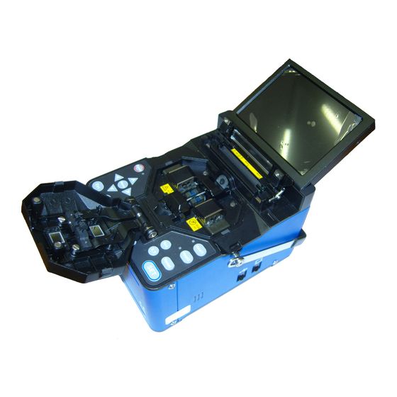
Summary of Contents for Ilsintech Keyman S1
- Page 1 Instruction manual Optical fiber fusion splicer Keyman S1 Please read through this manual completely before its first use.
-
Page 2: Table Of Contents
Contents I. Safety guide II. Product structure 1. Parts of the splicer 2. Requirements for splicing III. Product guide 1. Outward of the main body 2. Parts for fusion splicing IV. Using method 1. Power supply V. Instructions for use 1. - Page 3 2. Select Heater Mode 3. Arc calibration 4. Splice Option 5. Splice Memory VIII. Sub Menu 1. Language 2. Power Save 3. Menu Lock 4. Other Option IX. Auxiliary menu 60 60 1. Replace Electrodes 2. Stabilize Electrodes 3. Clear Arc Count 4.
- Page 4 4. Maintenance information Ⅼ. Q & A 1. Power supply 2. Splice operation 3. Tube heater operation 4. Management 5. Other settings Ⅽ. PC Program set up 1. PC Program set up Ⅾ. Warranty period and contact address 1. Warranty period and limitation 2.
-
Page 5: Safety Guide
Ⅰ. Safety guide Keyman S1 has been designed and manufactured for convenient use in indoor or outdoor working conditions. It is easy and simple to use, but please read through this manual completely to avoid failures and safety accidents before you use it. - Page 6 Do not give severe vibration or shock to the battery. If the battery is not fully charged within 6 hours or green LED lamp is not on, immediately stop charging and contact Ilsintech(Inc.) Do not place any object on AC adapter during charging.
- Page 7 Warning Only use the specified battery charger(S-11). Do not use AC power other than the allowable power indicated. Do not let battery(S-1B) or the terminal of the specified charger be short- circuited. Excessive current flow may cause damage to the equipment and persons.
- Page 8 Do not store the equipment in high-temperature or high-humidity conditions. Equipment damage could occur. Qualified experts should check up technical matters concerning S1. Not doing so may cause fire or electric shock. Please contact qualified service personnel in Ilsintech(Inc.) and get A/S service.
-
Page 9: Product Structure
Ⅱ. Product Structure 1. Parts of the splicer S1 main unit S-1B battery pack S-11 battery charger AC cord Other accessory items - Carrying case - Instruction manual... -
Page 10: Requirements For Splicing
Requirements for splicing Fiber type 0.25mm 0.9mm Basic sleeves Optical fiber length 40mm length 60mm protection sleeves Micro sleeves length 20mm length 25mm length 34mm length 45mm Coating stripper Optical fiber stripping tools Optical fiber cleaver [CI-03] Optical fiber cleaving tools Optical fiber holder [FTTH] Optical fiber holder [standard] cleave length : 10mm (fixed) -
Page 11: Product Guide
Ⅲ. Product guide Keyman S1 is an optical fiber fusion splicer, designed to connect various optica fibers using DCA technology. S1 is a light, small and convenient device with lo splice loss and fast splice speed suitable for both indoor and outdoor working conditions. - Page 12 connection Connection jack for Connection jack for Connection jack for the jack external monitor (RCA (USB 2.0) specified charger xternal DC power and jack) back-up battery. eater1 movement lam Power indicator Heater 2 movement lamp Power switch Heater 1 key (top heater) Heater 2 key (low heater) Curso r ke...
-
Page 13: Parts For Fusion Splicing
2. Parts for fusion spl icing electrode Camera illumination cover Y-axle camera Sleeve lauder p electrode Fixed left fiber co Fixed right fiber cover Groove to install sleeve lauder Groove to install sleeve lauder Illumination for night work Lower electrode Lower electrode X-axle camera cover... -
Page 14: Using Method
Ⅳ. Using method 1. Power supply The highly efficient built-in battery of S1 enables to use SI without attaching additional battery. Charging the battery If the specified charger is connected to “Charger” Jack on the left to the main unit and the AC cord to AC outlet, the charging LED lights up red, green and yellow in sequence and charging starts when the LED lights up red... - Page 15 When yellow LED blinks, disconnect the AC cord and connect it again after ten minutes. Protective devices are built in the battery of S1(S-1B) and so prevent over arc, over charge and overload. When these protection functions are performed, its power is automatically shut off.
- Page 16 At this time, charging does not work. Only use the specified voltage. Do not (DC 12V car cigar-jack) simultaneously use the cigar-jack for the splicer and other products. The car battery could be overpowered. Large-capacity battery(S-SB) use Have an optional large capacity battery(S-SB) installed on the lower part of S1 and connect the connection cord to “DC IN 12V”...
- Page 17 Battery remaining remaining capacity display Remaining capacity indicator (LED) capacity (Monitor) 80 ~ 100% (5 bars) 5 LED 60 ~ 80% (4 bars) 4 LED 40 ~ 60% (3 bars) 3 LED 20~40% (2 bars) 2 LED 1 LED (1 bar) Within 5 % (Immediate charge 1LED blinks...
-
Page 18: Instructions For Use
Ⅴ. Instructions for use 1. Function keys This i s Power ON and OFF key. If you press the key, power is on, the moni tor is turned on and next square indicator lights up red. If you press it for about one second again, the lamp turns off and power turns off. -
Page 19: Turning On S1
Battery remaining capacity display key. If you press this key one time, battery remaining capacity LED lights up and then off one second later. This command key is to execute splicing. Next movement in the case of section operation This key is used to cancel splicing or initialize the splice function. This key is to convert the splicing screen. -
Page 20: Installing The Protection Sleeve Lauder
Home screen Monitor brightness Set a value with leftward or rightward cursor key and press the ENTER key to change Monitor brightness. Splice mode Select a proper splice mode for exact splicing. The current splice mode is displayed on the home screen. -
Page 21: Inserting Optical Fibers Into Protection Sleeves
5. Inserting optical fibers into protective sleeves Push an optical fiber into a protective sleeve. Sleeve Optical fiber 6. Cleaning and stripping optical fibers Strip about 4 cm of coating from the fiber end with a coating stripper. Clean the bare fiber by wiping it with a lint-free tissue soaked in alcohol. -
Page 22: Placing The Fiber In The Splicer
Remove the cut end of the fiber and throw away in a proper container. For more details concerning the use of cleaver, refer to the cleaver instruction guide. 8. Placing the fiber in the splicer. Open the wind protector and the fiber clamp holder. -
Page 23: Splicing Procedures
9. Splicing procedures You can observe the optical fiber by using the image processing system installed in Keyman S1. But your naked eyes are also necessary to inspect the monitor for more complete result of splicing. Optical fibers placed in the splicer move towards each other. - Page 24 After the alignment of fibers, arc is performed for splicing. Press the Arc key after the completed alignment in the case of step–by-step movement. Then, arc is performed. The estimated splice loss value is displayed monitor after completed splicing. The loss value is affected by various error factors.
- Page 25 In some cases, splice loss can be even worsened by additional re-arc. You can set additional re-arc to OFF or limit the number of re-arc.
- Page 26 Increase in splice loss: cause and improving measures symptom cause solution Core axle Dust in the V-grooves and fiber Clean the V-grooves and Off set holder chips fiber holder chips. Core angle Dust in the V-grooves and fiber Clean the V-grooves and holder chips fiber holder chips.
- Page 27 thick Too long optical fibers. Decrease overlapping thin Improper ARC POWER Adjust ARC POWER Adjust initial ARC POWER, A few improper arc-affecting initial time factors overlapping. line Adjust initial ARC POWER, A few improper arc-affecting initial time factors overlapping. Sometime s a vertical line appears in the splice point during splicing multi-mo de optical fibers or dissimilar fibers(with different diameter).
-
Page 28: Removing Spliced Optical Fibers
10. Removing spliced optical fibers Open the lid of the tube heater. Open the wind protector. Grasp and hold the left fiber with the left hand at the edge of wind protector and open the lid of left fiber clamp holder. -
Page 29: Heating The Protection Sleeve
12. Heating the protection sleeve Transfer the fiber with protection sleeve to the center of the tube heater. Place the fiber with protection sleeve in the tube heater. Be sure to keep tension downwards on the fiber as it is placed, so that the tube heater lid can automatically close. -
Page 30: The Maintenance Of Quality Splice
Ⅵ. The maintenance of quality splice 1. Cleaning and inspection before spli cing For the cleaning and maintenance of important areas, refer to the following. Cleaning of V-grooves Contaminants in V-grooves do not assure proper holding, resulting in high splice loss. V-grooves must be frequently inspected and regularly cleaned up even during its daily operation. - Page 31 chip Cleaning of the fiber clamp holder Contaminants in holder clamp chip do not assure proper holding, resulting in low- quality splicing. Holder clamp chip must be frequently inspected and regularly cleaned up even during its daily operation. To clean V-grooves, see the following. Open the wind protector.
-
Page 32: Regular Inspection And Cleaning
2. Regular inspection and cleaning Regular inspection and cleaning are required to maintain high-quality splice. Cleaning of the object lenses Contamination on the surface of the lens makes it difficult to recognize the fiber core position, resulting in high splice loss. If this happens, the splicer fails to work properly. To prevent this, clean two object lenses at regular intervals. - Page 33 Replacement of the glass of wind protector If the fiber image is not clear enough, or the stain remains even after the clean-up, replace the glass. Turn off the splicer. Open the wind protector. Remove the glass with a cross-head screwdriver. Take care of the spring on the back when removing.
- Page 34 Blade position adjustment If the cleaver fails to work properly, rotate the blade 1/16 of a turn to replace the worn out blade position with a sharp blade position. To rotate the blade, see the following. Loosen the wrench bolt a little on the right of the cleaver with the hex wrench on the lower part of the cleaver.
-
Page 35: Main Menu
Ⅶ. Main Menu 1. Select Splice mode The optical splice setting for the exact optical fiber assembly comprises the splicing factors described below. These factors are dependent on optical fiber assembly and the difference in optical fibers. A factor to adjust arc/heating A factor to calculate estimated loss A factor to adjust fiber alignment and splicing process The limit value for an error message... - Page 36 Mode for splicing the multimode fiber. Core diameter: 50.0 ~ 62.5um AT1/AT2 Attenuation splice Others are not mentioned above and stored in the database of the splicer. OTHERS New splice modes will be added continuously. For more information concerning recent new modes, contact Ilsintech(Inc.)
- Page 37 Selecting a splice mode Select a splice mode suitable for the prepared optical fiber. Ready Press the menu key in ready, pause 1, pause Home screen 2 or finish state, and the splice menu appears. Select the Splice Mode menu, and Selec Splice Mode appears.
- Page 38 Creation or deletion of a splice mode Select “BLANK” from [Select How to create a splice mode Splice Mode] Nine splice modes are originally stored in splicer other modes displayed as blank. Select splice mode Select “BLANK” from Select Splice Mode and press the right arrow and the ENTER key.
- Page 39 Reference or splice mode edit Select the edit mode Splice factors in each splice mode can be modified. ARC POWER and arc time, above all, are the most important factors, and to Edit mode edit the two factors, refer to the following. Move the cursor to change the splice mode on Edit Mode menu.
- Page 40 Below is the list of splice factors for AUTO, SM, DS, MM and NZ modes. For easy operation, a limited number of factors described below are displayed on the screen in the SM, DS, MM or NZ mode. Additional factors not mentioned below are set to proper values in the production process.
- Page 41 Splice edit mode The splice mode edit enables users to set various splice modes and use them in a proper way in their working conditions. Instructions for using various parameters and their functions are described below. Parameter Description The list of splice modes stored in the splicer database appears on the screen.
- Page 42 conducted to remove fine dust on the fiber surface. The execution time of cleaning arc is set in this domain. It sets the section gap between left and right during alignment and initial arc. It sets the position of the fiber to splice at the center of arc. If the MFD values of left and right fibers are different, splice the fiber Gap set Position with the smaller value.
- Page 43 It sets re-arc time. It automatically sets re-ARC POWER in the [splice mode edit] Re-arc time menu to arc the same amount as [ARC POWER 2]. If ARC POWER 2 is set to ON and OFF, re- arc is automatically set to ON and OFF. Thin fibers increase splice loss in isolated cases.
- Page 44 How to insert mode title / note / password Select a mode title / note / password, and the letter list is displayed below. Select the desired text moving the cursor and press the ENTER key to input. If the text input is completed, move to [finish] by moving the cursor and press the ENTER key to finish.
-
Page 45: Select Heater Mode
Database parameter Description A mode to heat standard 60mm sleeves. S-160 Ilsintech S-160 A mode to heat standard 40mm sleeves. S-140 Ilsintech S-140 34mmA A mode to heat standard 34mm macro sleeves... - Page 46 Selecting heater mode Select a heater mode most suitable for the optical fiber protection sleeve to use. Select [Select Heater Mode] in [Main Select [Select Heater Mode] in menu], and [Select Heater Mode] is [Splice menu] displayed. Select heater mode Select a heater mode using the key, and press the ENTER key.
- Page 47 Parameters description • sleeve type setting • The list of all heater modes is displayed. Sleeve type • The user can copy the wanted program mode or select it from the list. • heater mode title is displayed on right lower side of the screen Mode title 1 during splicing and heating.
-
Page 48: Arc Calibration
3. ARC CALIBLATION ARC POWER can be adjusted according to the change in air temperature, humidity and pressure. The sensor for temperature, humidity and pressure makes it possible to calibrate Arc Power properly in accordance with surrounding conditions. The change in ARC POWER caused by the electrode wear and fiber splicing is not automatically adjusted. - Page 49 After the measurement is completed, the result such as the following is displayed on the screen. Arc Calibration Select [ ] in “Test Finish” message [Splice menu]. arc voltage This message means that calibration and splice position are successfully completed. Press the Esc key Arc Calibration to finish this function.
-
Page 50: Splice Option
4. Splice Option This function can set general parameters of all modes for splicing and tube heater operation. Select [Splice Option] in [Main menu]. Select [Splice Option] in [Main menu]. Splice composition menu is displayed. You can change and select some Splice setting parameters. -
Page 51: Splice Memory
5. Splice memory Select [Splice Memory] in [Main The memory of this splicer can store menu] more than 2000 splice results. The purpose of data storage is to store the result in the splice mode without relying on other things. Splice result setting Data Display Splice results stored in the memory can be displayed. - Page 52 Clearing Memory The splice results stored in the memory can be cleared partially or completely. Select [Clear Memory] in [Splice Memory], and the [Clear Memory] menu appears. CLEAR ALL DATA Move to [CLEAR ALL DATA] and press the ENTER key. The selection window of “Yes”...
- Page 53 Select [SPLICE MEMORY].
-
Page 54: Sub Menu
Ⅷ. Sub menu This Sub Menu is divided into details. Each detailed function menu can change the motions of the splicer. Press the Menu key and move to the Sub Menu using the cursor. Select and change each condition. 1. Language Screen position change operation Select language on the Sub Menu screen and press and language state is... -
Page 55: Power Save
2. Power Save The power saving function is important for energy preservation. If the battery pack is used without the power saving function set, the number of splicing gets decreased. For that reason, the power saving function is recommended. The power saving function setting is as follows. Select [Power save] in [SUB menu] Power Save... -
Page 56: Menu Lock
3. Menu Lock Select Menu Lock in [Sub Menu] and press the Enter key. Select Password Lock From and press the [ENTER] key, and the password input screen is displayed. Select letters to create your password using the cursor and move the cursor to Finish and press the [ENTER] key. - Page 57 Select Splicer Mode and press the menu to set or cancel the splicer mode lock appears. If “yes” is selected, a warning window saying “Password Locked” is displayed when you try to change a splice mode set value. You cannot change the value. If you select Heater Mode, you can choose to set or cancel the heater mode lock.
- Page 58 If you select Splice Results, you can choose to set or cancel splice results lock. If you select “yes,” you can not clear splice results. If Password Lock From is set to “yes” and Mode lock is not set to “yes,” lock function does not work.
-
Page 59: Other Option 5
4. Other Option Other Option in Sub Menu provides information on other functions including setting method. If you select System Settings, you can change password and buzzer sound. Please remember the password. If you forget it, you have to send the splicer to the factory for maintenance. - Page 60 Program Version menu enables you to confirm the input program version. If you select Arc Calibration, you can set the angle limit when calibrating arc power.
-
Page 61: Auxiliary Menu
Ⅸ. Aux menu 1. Replace Electrodes As the splicer is used, the electrode is worn out and silica oxidized substances are accumulated. Therefore, regular cleaning is needed. It is recommended to replace the electrodes after approximately 2,000 arcs. A message indicating the electrode replacement appears after more than 2,000 arcs. If this happens, turn off the splicer and replace the electrodes. - Page 62 Be careful not to give damage to the electrode while replacing it. Tighten the screw while pressing the electrode retainer in the exact position. Turn on the splicer and press the [ENTER] key after preparing optical fiber. Perform an arc repeatedly about 4 times to make the electrodes stable after the arc calibration.
-
Page 63: Stabilize Electrodes
2. STABILZE ELECTRONODES Sometimes, arc power becomes unstable due to surrounding conditions, increasing splice loss. It takes a long time to stabilize arc power when the splicer is at too low or high positions. With this in mind, continue to calibrate arc power until the electrode in the case gets stabilized. -
Page 64: Clear Arc Count
3. CLEAR ARC COUNT This function deletes the arc number. Select [Clear Arc Count]. Select “yes” and press the ENTER key to clear the arc number. Perform this function after “electrode replacement” is completed. 4. SET CALENDER This function sets the time and date to store in the splicer. -
Page 65: Sensor Value
5. SENSOR VALUE The current temperature, pressure, humidity and battery voltage are displayed by various Sensors. -
Page 66: Error Messages
LED lighting is dark. ⇒ Press the Reset key and reset the fiber. Remove the contaminants on the lens and moving mirror ⇒ If an error is confirmed by LED check up, refer to Ilsintech(Inc.). -
Page 67: Fiber Over Angle
4. FIBER OVER ANGLE This error message appears when the measured cleave angle of the fiber exceeds the limit value of the angle. ⇒Check the condition of the cleaver and reset the fiber. ⇒Check the limit value of the cleave angle. 5. -
Page 68: Core Bubble
8. CORE BUBBLE This error message appears when a bubble or a spot occurs at the splice point after splicing. ⇒ Check the fiber cleaver. ⇒ Clean the V-Groove. ⇒ Check the electrodes. -
Page 69: Solutions To Splicing Problems
Ⅺ. Solutions to splicing problems If the loss limit is higher than expected after splicing or abnormal splice operation is found, take proper measures according to the following. 1. High loss Limit Dust or foreign substance may cause poor splicing. ∙... -
Page 70: Abnormal Splice Operation
∙ Open the wind protector and close it again. ∙ If an error occurs when the wind protector is opened, press the Reset button and turn off the splicer and contact Ilsintech(Inc.). TOO LONG FIBER error is repeated. ∙ Reset and turn off the splicer and contact Ilsintech(Inc.). -
Page 71: Ⅻ. Other Menus
Ⅻ. Other Menus 1. Diagnostic Test A simple diagnostic test can be conducted for all functions of Keyman S1. This test provides information on whether the splicer is properly working. Procedures Place optical cable in the splicer and select [Diagnostic test] in the menu. -
Page 72: Motor Drive
Press the Esc key to finish the dust inspection. If dust remains on the glass or object lens even after cleaning, contact Ilsintech(Inc.). 3. Motor Drive Six motors in the splicer can be operated in the passive mode. In addition, a motor can be operated by calling this menu in [Pause 1] and [Pause2] during the splicing process. -
Page 73: Maintenance Information
4. Maintenance Information Select [Maintenance Information], and the following is displayed. Parameter Description Produce Displays the manufacturing date of the splicer (year, month, day) Displays the arc number after an electrode is replaced. Electric number If [Clear Arc Count] in [Aux Menu] is executed, the number is initialized to ‘0’. -
Page 74: Ⅼ. Q & A
This also happens when there is a defect in the battery pack or its use period is over. If the LED still blinks after installing a new battery pack, contact Ilsintech(Inc.). LED fails to turn on during charging. -
Page 75: Splice Operation
Splice loss is affected by cleave angle, arc condition and clean or dirt condition of the fiber. If the splice loss remains high or unstable after taking the measures described above, please contact Ilsintech(Inc.) The splicer requires regular, annual maintenance to keep splice quality. Check the splice procedures. - Page 76 The splicer turns off all of a sudden. Turn on the splicer again and check Power-Save menu. How to change the error limit value for cleave angle, splice loss and fiber angle. See [Splice Mode Edit]. An error message can be ignored. See [Additional splice functions].
-
Page 77: Tube Heater Operation
The heater is overheated. Press the Heater key to stop the operation and turn off the splicer. Then contact Ilsintech(Inc.). A fiber protection sleeve remains on the heating plate after shrinking. Please use a cotton swab or a similar tool to push or remove the sleeve. -
Page 78: Other Settings
Refer to [Menu Lock]. If you forget the password Please contact Ilsintech(Inc.). 5. Other settings Repeatedly perform [Arc Calibration] function until “Test Finish” is displayed. The splicer requires extensive calibration when the electrodes are replaced or surrounding conditions go through a considerable change. -
Page 79: Ⅽ. Pc Program Set Up
C. PC Program set up 1. PC Program set up procedure of XP Download FT Driver at your PC. Connect Fusion splicer and PC by using USB. Check & Install “USB Serial Port”. Choose “Install from a list or specific location(Advanced)”, and click the next button. - Page 80 Click the finish button. “When USB Serial Converter Driver” is installed, “Found New Hardware Wizard” will be appeared again. Select “Search for the best driver in these locations” and click “Include this location in the search”, and choose the saved location of FTDRIVER in Browse.
- Page 81 Click the Finish button and USB Serial Port installation is completed. Click [My computer ] and then press right but ton, choose properties. Click [hardware] folder in system registered information window, and then click [Device Manager] folder.
- Page 82 Click [port(COM and LPT)] in operator window, and choose “USB Serial Port” folder. Take [ Port Se ttings] folder in USB Serial Port window, and set “115200”.
- Page 83 Click “Advanced Settings for COMx” folder in the bottom of window and then Go to “COM Port Number”. Take your wanted port in COM3 ~ COM10 and then click “O.K” for confirmation. Execute S1 splicer program, and choose COMx Port same as in Advanced Settings for COMx window.
- Page 84 When splice data is transmitted to PC, it is shown as the order of date and time at <Splice Results> window. When you click, a certain data, the detailed data is shown at <Detail Display> window. Document file(S1.txt) of splice result will be created in the relevant [folder] or [desktop] which is installed with S1 splicer program.
-
Page 85: Ⅾ. Warranty Period And Contact Address
Ⅾ. Warranty period and contact address 1. Warranty period and limitation Ilsintech(Inc.) provides free repair service for the purchased product if it fails to work Regardless of the warranty properly for a period of one year from the date of delivery. -
Page 86: Splicer Transportation
4. Splicer transportation Keyman S1 is a precision instrument. When transporting the splicer, use its specified transport case to protect it from moisture, shock and impact. If your fusion splicer needs servicing, please place the splicer and its accessories in the transport case and send them to us. - Page 88 3. When you seek repair for the product, please present this warranty with it. 4. Keyman S1 is a precision instrument. When transporting the splicer, use its specified transport case to protect it from moisture, shock and impact.
- Page 89 Tel : +82-42-671-5609~11 http:// www.ilsintech.com E-mail : rnd@ilsintech.com...
Need help?
Do you have a question about the Keyman S1 and is the answer not in the manual?
Questions and answers