
Related Manuals for Ilsintech Keyman S1


Summary of Contents for Ilsintech Keyman S1
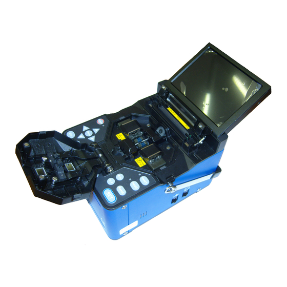
- Page 1 Ilsintech Keyman S1 Specs Provided by www.AAATesters.com Maintenance Manual Optical fiber fusion splicer Keyman S1 Please read through this manual completely before its first use.
- Page 2 INDEX I . Safety guide II. Menu Control 1. Pop-up Menu Registration 2. Setting Auto Heat 3. Setting Errors to be Affected or Ignored 4. Menu Clearing the Record of Total Number of Electric Discharge 5. Setting the Amount of Electric Discharge to be Cleared 6.
- Page 3 7. Splice data Update IV. Maintenance 1. When an Error in Classifying SM and MM in Auto Mode Occurs 2. Eccentricity of Position of ARC Discharge 3. Abnormal Arrangement of Optical Fibers in Connection Operation 4. Occurrence of a Length Difference When Optical Fibers are Initially Placed 5.
- Page 4 It is easy and simple to use, but please read through this manual completely to avoid failures and safety accidents before you use it. Keyman S1 is designed to easily use, but also contains potential danger. Therefore, this manual contains all necessary instructions to assure safe splice.
- Page 5 If an abnormal condition such as the following occurs, immediately turn off power and disconnect the power source. Next, contact the maintenance service personnel in Ilsintech(Inc.). If unusual smoke, noise or odor or unusual overheating occurs, If foreign substance or liquid gets inside the splicer, or If the splicer is dropped from a high place or suffers damage Do not use AC power code other than the allowable power cord indicated.
- Page 6 Warning Do not use a voltage other than the allowable power voltage indicated. AC power supply for the specified charger is AC 100-240V, 50-60Hz. Please check the AC power supply before using. AC power supply within the improper range may cause electric shock, equipment damage, serious injury or even a death.
- Page 7 Do not give severe vibration or shock to the battery. If the battery is not fully charged within 6 hours or green LED lamp is not on, immediately stop charging and contact Ilsintech(Inc.) Do not place any object on AC adapter during charging.
- Page 8 Warning Only use the specified battery charger(S-11). Do not use AC power other than the allowable power indicated. Do not let battery(S-1B) or the terminal of the specified charger be short- circuited. Excessive current flow may cause damage to the equipment and persons.
- Page 9 equipment loss or injury. Wear safety glasses for protection from glass fibers. Glass fibers may cause serious damage to eyes or skin tissue. Do not use the splicer in high temperature conditions. Doing so may cause equipment loss or injury. Do not use a splicer in high temperature conditions.
- Page 10 During or after heating protection sleeves in the tube heater, do not touch both parts. Injury from high temperature could occur. Do not place S1 in unstable locations. If the equipment is dropped, injury or equipment damage could occur. S1 is a precision instrument. It should be handled with care and precision. When transporting it, use its specified transport case to protect it from dust, dust, moisture, shock and impact.
- Page 11 Equipment damage could occur. Qualified experts should check up technical matters concerning S1. Not doing so may cause fire or electric shock. Please contact qualified service personnel in Ilsintech(Inc.) and get A/S service. Ⅱ. Menu Control 1. Pop-up Menu Registration...
- Page 12 Both Connection Mode and Heater Mode can be registered in Pop-up menu, which allows user to select each mode in a quick manner by pushing either up or down direction key. Push ⇒ To activate a mode, select the mode by moving the cursor and then push key.
- Page 13 2. Setting Auto Heat The function of setting auto heat is useful, especially, in performing consecutive connection works. When the wind protection cover is opened after completing a connection, the heater starts to be operating and stops at the end of pre-set time period.
- Page 14 Menu Key → Aux → Select CLEAR ARC COUNT, in which push, simultaneously, both X, Y Key and Key. The total number of electric discharge becomes 0 when selecting Initialize and pushing Enter key. 5. Setting the Amount of Electric Discharge to be Cleared The electric discharge amount to be cleared can be set.
- Page 15 Ⅲ. Correction Menu 1. Selecting Correction Menu Push Menu Key → SUB → OTHER → Select System Setting → in which screen, push, simultaneously, both X, Y Key and Key. 2. 2. LED Bright Menu This menu is used for adjusting the brightness of camera flashes. A sub menu appears when selecting this menu.
- Page 16 select Menu Key → OTHER → LED CHECK, in which keep the brightness value between 80~86. LED Bright (Auto) This is an automatically adjusted brightness value of LED flashes which is applied when the device is booted. The standard value has been set to 83. 2.
- Page 17 Limittion Re-arc times Menu for setting re-arc discharge times The number set is the maximum times allowing re-arc discharge.
-
Page 18: Motor Setting
2. 5. Motor Setting Menu for setting measuring values of camera motor and X, Y motor The initial setting value of each motor shall be recorded prior to Up-Grade. A screen as next figure appears upon selecting the menu. Core Equalization Menu for correcting images from the camera Auto Mode: Menu for setting the reference position of the camera in Auto Mode... - Page 19 Menu for correcting image data of optical fibers in Auto Mode Fiber Type Resister: Menu for setting a standard value for recognizing Fibers in Auto Mode The value is (Do not change the initially set value). automatically adjusted when correcting the motor. Fiber Type Limit: Menu for setting a threshold value for recognizing Fibers in Auto mode (Do not change the initially set value).
- Page 20 Fiber Shape Set 1: A standard value used for judging the faulty status of a cut section of optical fibers (Clad Section). The bigger the size of this value is, the less sensitive the fault detection capability becomes. 1Fiber Shape Set 2: A standard value used for judging the faulty status of a cut section of optical fibers’...
- Page 21 1. When an Error in Classifying SM and MM in Auto Mode Occurs, Correct the error according to following steps; Push Menu Key → Select OTHER Menu → Select DIAGNOSTIC TEST. Place SM Optical Fiber → → Completion of Correction → ESC → Return 2.
- Page 22 the focus of the camera. Locate and set the position where no malfunction occurs by increasing or decreasing the value after selecting Except Auto Mode. 4. Occurrence of a Length Difference When Optical Fibers are Initially Placed In case that a length difference occurs when optical fibers are initially placed, first of all, remove all dirt in the V-Groove and clean optical fibers, and re-verify the status.
- Page 23 Increase Y-M toward + direction when it is higher. Increase Y-M toward – direction when it is lower. Select Motor Drive in Other Menu after conducting Set, return and then initialize the camera.
- Page 24 5. Occurrence of an Error during Booting Camera Led error Upon conducting Self Check after inputting power, if Camera Led error is displayed;...
- Page 25 Dust Check Error Upon conducting Self Check after inputting power, if Dust error message is displayed;...
- Page 27 9 6. In case of High Connection Loss Rate Check the status of electrode and replace it, if it has worn down. If the electric discharge shows an inclination toward the right or left side in the screen upon connection, correct the center of discharge by selecting Arc Position in Correction Menu.
- Page 28 Replace the batter after removing battery cables. 8. Replacing the Mirror Replacement of Wind Protection Cover Mirror The mirror shall be replaced, if unable to make it clean or remove stains by cleansing.
- Page 29 Turn off the fusion splicer Open the wind protection cover and detach the mirror using a (+) type screwdriver. Use extra caution in separating the mirror because a spring is place behind the mirror. Take out the shaft pin placed in the old mirror and insert it into the new mirror, and reassemble it in the reverse order of disassembling.
-
Page 30: Program Upgrade
Y screens while changing the screen by pushing X/Y keys. 9. Program Upgrade Data may be changed when Program Upgrade is done; therefore, it is required to separately keep the record of Set values of Correction Menu and verify them after completion of Upgrade. - Page 31 When a PC message indicating the detection of a new hardware appears, install FTDRIVER by selecting install. Set the PC as follow; Select Control Panel → System → Hardware → Device Manager → Port After selecting USB (COM3), complete the Port setting as given by following figure.
- Page 32 In Windows’ All Programs, go to Accessories → Communication → execute Hyper Terminal When an error message appears, click Confirm and continue the process. If a New Connection box appears, enter any number into it and click OK. If an error message pops up, click OK and continue the process. ※...
- Page 36 When setting the port is completed, select Transfer in the full down menu of Hyper Terminal and click Send. Select Upgrade Program Keyman S1_X_XX.bin File, which is saved in the PC, by clicking Brows button of Filename. Select Xmodem as a protocol, and click Send.
- Page 37 When a message as below appears after the file transfer is completed, turn off the power by pushing emergency reset button. Push, simultaneously, both ESC key and Power Key together (If the Logo screen is displayed without freezing the screen and the interface adapter is operated, perform it again after turning off the power).
- Page 39 Once the transfer is completed, the interface adapter is automatically booted with an alarm sound. Turn off the power and remove the USB Cable.
Need help?
Do you have a question about the Keyman S1 and is the answer not in the manual?
Questions and answers