
Related Manuals for Motomaster Eliminator 011-2103-8


Summary of Contents for Motomaster Eliminator 011-2103-8
- Page 1 1500 W PURE SINE INVERTER 3000 W PURE SINE INVERTER model no. 011-2103-8 (1500 W) / 011-2104-6 (3000 W) IMPORTANT: INSTRUCTION Please read this manual carefully before running this power inverter MANUAL and save it for reference.
- Page 2 With over 600 individual automotive products, MotoMaster has ® helped keep Canadians on the go by providing well-priced automotive products with competitive performance and durability.
-
Page 3: Table Of Contents
TABLE OF CONTENTS Safety Information Welcome A Higher Wattage Inverter May Be Required Warnings, Cautions and Notes Warnings: Inverter Output Cautions: Inverter Operating Environment Power Requirements Getting Started Front Panel LCD Diagram & Remote Instructions Rear Panel & Cables Gauges Hardwiring Instructions Select Battery Type Understanding battery amp-hour capacity with your application... -
Page 4: Safety Information
Please read this manual thoroughly before It is very important that any operator and installer ® installing and operating your new MotoMaster of this inverter read and follow all WARNINGS, Eliminator inverter. This manual contains CAUTIONS AND NOTES and all installation and information you need to obtain the performance operation instructions. -
Page 5: Cautions: Inverter Operating Environment
Damage caused by reversed polarity is not covered under the MotoMaster ® warranty. • Making the connection to the positive terminal... -
Page 6: Power Requirements
INSTALL A FUSE Battery banks can deliver very high levels of current that can vaporize metal, start fires and cause explosions. Motomaster ® recommends installing one ANL type fuse and fuse holder close to the positive battery bank terminal. This fuse protects the batteries from accidental DC cable shorts, which can... -
Page 7: Getting Started
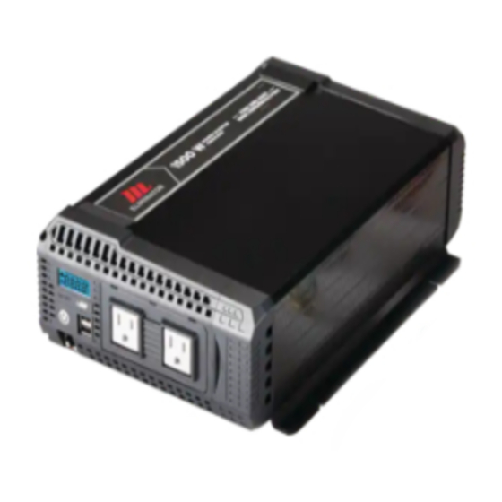
FRONT PANEL LCD Digital Display (see LCD diagram on Two USB Ports QC3.0 (5V/3A, 9V/2A, 18W max) next page). Two standard North American AC outlets, MENU Button: Pressing the button will each rated at 15 A change the display between OUTPUT Hardwire terminals WATTAGE, INPUT/OUTPUT VOLTAGE or INTERNAL TEMPERATURE... -
Page 8: Lcd Diagram & Remote Instructions
model no. 011-2103-8 / 011-2104-6 | contact us 1-888-942-6686 LCD DISPLAY Battery Level (25%, 50%, 75%, 100%). Output Wattage (W), Input Voltage (VDC) or Output Voltage (V) Display. Temperature Shutdown. Warning Indicator: High voltage b. Low voltage Overload Error. Remote Instructions The included remote control features an LED indicator showing on/off light, push button and 20' (6 m) cable that simply plugs... -
Page 9: Rear Panel & Cables Gauges
REAR PANEL Thermal Activated High-Speed Cooling Positive Power Input Terminal. Fans. When temperature inside inverter Negative Power Input Terminal. exceeds a preset limit, the cooling fans automatically turn on to cool the inverter. When the temperature reduces, the fans turn off. Ground Terminal. -
Page 10: Hardwiring Instructions
model no. 011-2103-8 / 011-2104-6 | contact us 1-888-942-6686 HARDWIRE INSTRUCTIONS This inverter comes equiped with an optional AC output hardwire connection to allow for direction connection to an off-grid electrical panel. All AC wiring ( inverter to AC panels, AC panels to circuit breakers, and GFCIs) must be rated to at the current rating of the fuses and/or circuit breakers. -
Page 11: Select Battery Type
The type of batteries you use to power your high-power inverter is important. Operating a high-power inverter will routinely discharge batteries and they will require frequent recharging. Batteries used to start engines are not designed to repeatedly charge and discharge. MotoMaster ® recommends using... -
Page 12: Understanding Controls And Features
® inverter should not be mounted under the hood of a vehicle. MotoMaster If installing in a vehicle, choose a dry, cool, ventilated area as close to the battery as practical. Before drilling any mounting holes, make sure that there are no wires, fuel lines or tanks directly behind the surface to be drilled to install the inverter : Inverter must be off. -
Page 13: Operation
OPERATION Ensure the inverter is OFF. Ensure the appliance to be operated is turned OFF and plug it's electrical cord into one of the AC outlet on the front of the inverter. Turn the inverter ON. Turn the appliance ON. Plug in and turn ON additional appliances as needed. -
Page 14: Troubleshooting
model no. 011-2103-8 / 011-2104-6 | contact us 1-888-942-6686 TROUBLESHOOTING PROBLEM POSSIBLE CAUSE SOLUTION The digital display • Low battery voltage • Recharge the battery. Check shows “LOW shutdown feature turns if cables and connections are VOLTAGE”. OFF the inverter. secure. -
Page 15: Specifications
SPECIFICATIONS: 011-2103-8 1500 W + 18 W USB Output Continuous Watts (W) Surge Capacity (Peak Power) 3000 W DC Input, Full Load DC Input Current 12V battery, 150 A Input Voltage Range 10.5 to 16 V DC +/- 0.3 V (auto reset) Rated Frequency (Hz) 60 Hz±1 Rated Output AC (V, A) -
Page 16: Warranty And Returns
This MotoMaster Eliminator product carries a three (3) year warranty against defects in workmanship and materials. At its discretion, MotoMaster Canada agrees to have any defective part(s) repaired or replaced free of charge, within the stated warranty period, when returned by the original purchaser with proof of purchase.
Need help?
Do you have a question about the Eliminator 011-2103-8 and is the answer not in the manual?
Questions and answers