Table of Contents
Advertisement
Quick Links
Dual Mode (WPC and PMA) Integrated Wireless Receiver
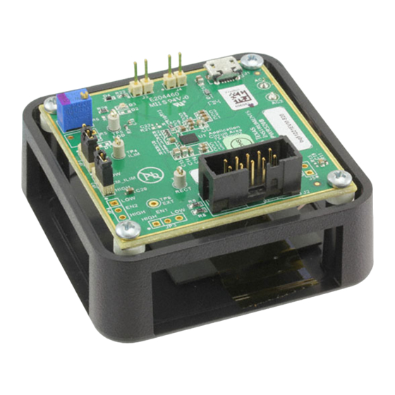
The bq51221EVM-520 (PWR520-001) wireless power receiver evaluation kit (EVM) from Texas
Instruments is a high performance, easy-to-use development kit for the design of wireless power solutions.
It helps designers to evaluate the operation and performance of the bq51221 IC, (also, this EVM can be
used to evaluate the bq51021 IC, a WPC-only receiver) a secondary-side receiver device for wireless
power transfer in portable applications. The bq51221 device is a fully contained wireless power receiver
capable of operating in both the WPC and PMA protocols which enables a system to not be confined to
one standard. The bq51221 provides a single stage power conversion while integrating the digital control
and communication. The bq51221 complies with the WPC v1.1 and PMA communication protocol. The kit
enables designers to speed up the development of their end-applications.
...................................................................................................................
1
2
3
4
5
5.1
5.2
5.3
5.4
5.5
6
6.1
6.2
6.3
6.4
.................................................................................................................
7
7.1
7.2
7.3
7.4
7.5
7.6
8
8.1
8.2
8.3
9
9.1
9.2
9.3
9.4
9.5
SLUUAX6B - February 2014 - Revised June 2014
Submit Documentation Feedback
..............................................................................................
..................................................................................................................
......................................................................................
.................................................................................................
............................................................................................................
..................................................................................................
............................................................................................
...........................................................................................
...............................................................................................................
.............................................................................................................
..................................................................................
....................................................................................................
............................................................................................................
..........................................................................................................
...............................................................................................
.....................................................................................................
.......................................................................................
.............................................................................................
...................................................................................
............................................................................................................
.....................................................................................................
...............................................................................................
...................................................................................................
.................................................................................................
........................................................................................
....................................................................................................
Dual Mode (WPC and PMA) Integrated Wireless Receiver Power Supply
Copyright © 2014, Texas Instruments Incorporated
SLUUAX6B - February 2014 - Revised June 2014
Contents
..........................................................................
...............................................................
.................................................................
.........................................................................
List of Figures
User's Guide
Power Supply
11
11
12
14
15
15
16
17
17
17
17
18
18
18
18
20
23
3
3
4
4
5
5
6
6
7
7
8
8
8
8
9
1
Advertisement
Table of Contents

Related Manuals for Texas Instruments bq51221EVM-520


Summary of Contents for Texas Instruments bq51221EVM-520
-
Page 1: Table Of Contents
Dual Mode (WPC and PMA) Integrated Wireless Receiver Power Supply The bq51221EVM-520 (PWR520-001) wireless power receiver evaluation kit (EVM) from Texas Instruments is a high performance, easy-to-use development kit for the design of wireless power solutions. It helps designers to evaluate the operation and performance of the bq51221 IC, (also, this EVM can be used to evaluate the bq51021 IC, a WPC-only receiver) a secondary-side receiver device for wireless power transfer in portable applications. - Page 2 Electrical Performance Specifications ....................... Pin Description ................bq51221EVM-520 Rev. B Bill of Materials Dual Mode (WPC and PMA) Integrated Wireless Receiver Power Supply SLUUAX6B – February 2014 – Revised June 2014 Submit Documentation Feedback Copyright © 2014, Texas Instruments Incorporated...
-
Page 3: Introduction
EVMs do not have RX ID implemented. Considerations with this EVM The bq51221EVM-520 evaluation module (PWR520-001) demonstrates the receiver portion of the wireless power system. This receiver EVM is a complete receiver-side solution that produces 5-W output power at up to 1-A load with adjustable output voltage. -
Page 4: Modifications
Note that changing components can improve or degrade EVM performance. Recommended Operation Condition Table 1 provides a summary of the bq51221EVM-520 performance specifications. All specifications are given for an ambient temperature of 25°C. Table 1. bq51221EVM-520 Electrical Performance Specifications Parameter... -
Page 5: Equipment And Evm Setup
T. Allag Contact: http://www.ti.com/support © Tex as Instruments 2014 Figure 1. bq51221EVM-520 Schematic SLUUAX6B – February 2014 – Revised June 2014 Dual Mode (WPC and PMA) Integrated Wireless Receiver Power Supply Submit Documentation Feedback Copyright © 2014, Texas Instruments Incorporated... -
Page 6: Connector And Test Point Descriptions
Connector and Test Point Descriptions The connections points are described in the following paragraphs: J1 – AD External Adapter Input Power can be provided to simulate an external adapter applied to the receiver in the bq51221EVM-520 (PWR520-001). J2 – Programming Connector This connector is populated and is used for I2C communication using the USB-TO-GPIO “HPA172”... -
Page 7: Test Point Descriptions
LPRB_EN and TERM LPRB1 and WPG COMM2 VO_REG ILIM CM_ILIM TMEM LPRB2 and PD_DET SLUUAX6B – February 2014 – Revised June 2014 Dual Mode (WPC and PMA) Integrated Wireless Receiver Power Supply Submit Documentation Feedback Copyright © 2014, Texas Instruments Incorporated... -
Page 8: Test Procedure
Test Procedure www.ti.com Test Procedure This procedure describes test configuration of the bq51221EVM-520 evaluation board (PWR520-001) for bench evaluation. Definition The following naming conventions are used: VXXX : External voltage supply name (VAD, VOUT, VTS) LOADW: External load name (LOADR, LOADI) V(TPyy): Voltage at internal test point TPyy. -
Page 9: Procedure
• Put the receiver EVM on the Transmitter coil and align them correctly SLUUAX6B – February 2014 – Revised June 2014 Dual Mode (WPC and PMA) Integrated Wireless Receiver Power Supply Submit Documentation Feedback Copyright © 2014, Texas Instruments Incorporated... - Page 10 250 ms and may cause fluctuation in the reading use lower value or base line) Dual Mode (WPC and PMA) Integrated Wireless Receiver Power Supply SLUUAX6B – February 2014 – Revised June 2014 Submit Documentation Feedback Copyright © 2014, Texas Instruments Incorporated...
-
Page 11: Test Results
VOUT and IOUT from the RX as the battery charges Figure 2. bq51221 in Steady State Operation with bq24250EVM SLUUAX6B – February 2014 – Revised June 2014 Dual Mode (WPC and PMA) Integrated Wireless Receiver Power Supply Submit Documentation Feedback Copyright © 2014, Texas Instruments Incorporated... -
Page 12: Load Step
Monitor on side RX: load current, rectifier voltage, and output voltage as shown in Figure 3 Figure 3. Load Step (PMA) with VIN_DPM Dual Mode (WPC and PMA) Integrated Wireless Receiver Power Supply SLUUAX6B – February 2014 – Revised June 2014 Submit Documentation Feedback Copyright © 2014, Texas Instruments Incorporated... -
Page 13: Load Step (Wpc)
Monitor on side RX: Rectifier voltage, and output voltage as shown in Figure 4 Figure 4. Load Step (WPC) SLUUAX6B – February 2014 – Revised June 2014 Dual Mode (WPC and PMA) Integrated Wireless Receiver Power Supply Submit Documentation Feedback Copyright © 2014, Texas Instruments Incorporated... -
Page 14: Ts Control Function
Monitor the TS pin, PMA signal (If a test fixture is used—to see End of Charge), WPG, and output voltage as shown in Figure 5 Figure 5. TS Control Function Dual Mode (WPC and PMA) Integrated Wireless Receiver Power Supply SLUUAX6B – February 2014 – Revised June 2014 Submit Documentation Feedback Copyright © 2014, Texas Instruments Incorporated... -
Page 15: Efficiency Data
Test Results www.ti.com Efficiency Data The plot shown in Figure 6 illustrates the system (DC-DC) efficiency of the bq51221EVM-520 under different transmitters. 0.90 0.80 0.70 0.60 0.50 0.40 0.30 WPC-bq500210_Vin_19 V WPC-bq500210_Vin_5 V 0.20 WPC-bq500410_Vin_12 V 0.10 PMA - 18 V 0.00... -
Page 16: Thermal Performance
Thermal Performance This section shows a thermal image of the bq51221EVM-520 in both WPC and PMA. A 1-A load is used and output voltage is set to 5 V. There is no air flow and the ambient temperature is 25°C. The peak temperature of the IC (39°C in WPC and 37°C in PMA) is well below the maximum recommended... -
Page 17: Dual Mode Coil Design Consideration
SLUUAX6B – February 2014 – Revised June 2014 Dual Mode (WPC and PMA) Integrated Wireless Receiver Power Supply Submit Documentation Feedback Copyright © 2014, Texas Instruments Incorporated... -
Page 18: Layout And Bill Of Materials
COMM1 = COMM2 = 300 mA • CLAMP1 = CLAMP2 = 500 mA • ILIM = 10 mA Dual Mode (WPC and PMA) Integrated Wireless Receiver Power Supply SLUUAX6B – February 2014 – Revised June 2014 Submit Documentation Feedback Copyright © 2014, Texas Instruments Incorporated... -
Page 19: Bq51221Evm-520 Layout Example
It is always good practice to place high frequency bypass capacitors next to RECT and OUT of 0.1 μF. Figure 11 illustrates an example of a WCSP layout. Figure 11. bq51221EVM-520 Layout Example SLUUAX6B – February 2014 – Revised June 2014 Dual Mode (WPC and PMA) Integrated Wireless Receiver Power Supply Submit Documentation Feedback Copyright ©... -
Page 20: Bq51221Evm-520 Layout
Layout Figure 12 through Figure 16 illustrate the bq51221EVM-520 layout views. Figure 12. bq51221EVM-520 Top Assembly Figure 13. bq51221EVM-520 Layer 1 Dual Mode (WPC and PMA) Integrated Wireless Receiver Power Supply SLUUAX6B – February 2014 – Revised June 2014 Submit Documentation Feedback Copyright ©... -
Page 21: Bq51221Evm-520 Layer
Layout and Bill of Materials www.ti.com Figure 14. bq51221EVM-520 Layer 2 Figure 15. bq51221EVM-520 Layer 3 SLUUAX6B – February 2014 – Revised June 2014 Dual Mode (WPC and PMA) Integrated Wireless Receiver Power Supply Submit Documentation Feedback Copyright © 2014, Texas Instruments Incorporated... -
Page 22: Bq51221Evm-520 Layer
Layout and Bill of Materials www.ti.com Figure 16. bq51221EVM-520 Layer 4 Dual Mode (WPC and PMA) Integrated Wireless Receiver Power Supply SLUUAX6B – February 2014 – Revised June 2014 Submit Documentation Feedback Copyright © 2014, Texas Instruments Incorporated... -
Page 23: Bill Of Materials
Layout and Bill of Materials www.ti.com Bill of Materials Table 3 lists the BOM for the bq51221EVM-520. Table 3. bq51221EVM-520 Rev. B Bill of Materials RefDes Value Description Package Reference Part No. Manufacturer 0.1uF CAP, CERM, 0.1uF, 50V, ±10%, X7R, 0603... - Page 24 Layout and Bill of Materials www.ti.com Table 3. bq51221EVM-520 Rev. B Bill of Materials (continued) RefDes Value Description Package Reference Part No. Manufacturer RES, 0 ohm, 1%, 0.063W, 0402 CRCW04020000Z0ED Vishay-Dale RES, 110 ohm, 1%, 0.063W, 0402 CRCW0402110RFKED Vishay-Dale Trimmer, 500 ohm, 0.25W, TH 4.5x8x6.7mm...
- Page 25 ..... • Added information in the abstract including the bq51021 IC as a device that can be evaluated with this EVM. SLUUAX6B – February 2014 – Revised June 2014 Revision History Submit Documentation Feedback Copyright © 2014, Texas Instruments Incorporated...
- Page 26 ADDITIONAL TERMS AND CONDITIONS, WARNINGS, RESTRICTIONS, AND DISCLAIMERS FOR EVALUATION MODULES Texas Instruments Incorporated (TI) markets, sells, and loans all evaluation boards, kits, and/or modules (EVMs) pursuant to, and user expressly acknowledges, represents, and agrees, and takes sole responsibility and risk with respect to, the following: 1.
- Page 27 RADIO FREQUENCY REGULATORY COMPLIANCE INFORMATION FOR EVALUATION MODULES Texas Instruments Incorporated (TI) evaluation boards, kits, and/or modules (EVMs) and/or accompanying hardware that is marketed, sold, or loaned to users may or may not be subject to radio frequency regulations in specific countries.
- Page 28 Les types d'antenne non inclus dans cette liste, ou dont le gain est supérieur au gain maximal indiqué, sont strictement interdits pour l'exploitation de l'émetteur. Mailing Address: Texas Instruments, Post Office Box 655303, Dallas, Texas 75265 Copyright © 2014, Texas Instruments Incorporated spacer Important Notice for Users of EVMs Considered “Radio Frequency Products”...
- Page 29 IMPORTANT NOTICE Texas Instruments Incorporated and its subsidiaries (TI) reserve the right to make corrections, enhancements, improvements and other changes to its semiconductor products and services per JESD46, latest issue, and to discontinue any product or service per JESD48, latest issue.
- Page 30 Mouser Electronics Authorized Distributor Click to View Pricing, Inventory, Delivery & Lifecycle Information: Texas Instruments BQ51221EVM-520...
Need help?
Do you have a question about the bq51221EVM-520 and is the answer not in the manual?
Questions and answers