Table of Contents
Advertisement
Quick Links
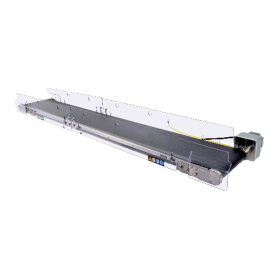
PF51 Conveyors
Installation Manual, Operation & Maintenance Instructions
Manuale d'installazione, funzionamento e manutenzione
Contents
/ Sommario
/
/
EC Declaration of Conformity
Dichiarazione di conformità CE
/ Documentazione manutenzione
Service Record
/ Inglese
Original Language: English
Translations from Original Language: Italian
/
/ Italiano
2
4
5
7
12
16
17
24
29
38
39
43
QC Conveyors
4057 Clough Woods Dr.
Batavia, OH 45103 USA
+1 (513) 753-6000
mcdonalds.qcconveyors.com
Advertisement
Table of Contents

Related Manuals for DURAVANT QC Conveyors PF51


Summary of Contents for DURAVANT QC Conveyors PF51
-
Page 1: Table Of Contents
PF51 Conveyors Installation Manual, Operation & Maintenance Instructions Manuale d’installazione, funzionamento e manutenzione Contents / Sommario / Avvertenze Warnings Dispositivo di controllo Controller / Installazione del trasportatore Conveyor Installation / Messa in servizio Commissioning / Funzionamento Operation / Manutenzione Maintenance / Tensione e allineamento Tension &... -
Page 2: Warnings / Avvertenze
Warnings Avvertenze When used improperly, conveyor Lock out power before servicing Do not use with guards removed Risk of Electrocution and Fire rollers can pinch or maim conveyor Se usati in modo improprio, i rulli del Prima di eseguire la manutenzione, Non usare se le protezioni non sono Rischio di folgorazione o incendio trasportatore possono creare piz-... - Page 3 Tools and Supplies Utensili e forniture u Tools and Supplies Utensili e forniture Wrench set ( 13mm, 10mm and Large and Small Flat Head & Torque Wrench with an 8mm 5mm Metric Allen Wrench 5.5mm) Large Phillips Head Screwdrivers Socket (Range 2- 8 Nm) Set di chiavi ( 13mm, 10mm e 5,5mm) Cacciaviti grande e piccolo a testa Chiave dinamometrica con una testa...
-
Page 4: Controller / Dispositivo Di Controllo
Controller Installation Installazione del dispositivo di controllo Lock-out power emergency stops are not included with the panels or conveyors. E-stops are required and must be installed as part of the tables. The circuitry for the E-stop is integrated in to the conveyor controller enclosure and requires a modular male connector. Additionally, installer must provide a lockable means of power isolation. -
Page 5: Conveyor Installation / Installazione Del Trasportatore
Conveyor Installation / Installazione del trasportatore Lock-out power. E-stops are required and must be installed as part of the tables. The circuitry for the E-stop is integrated in to the conveyor controller enclosure. Additionally, installer must provide a lockable means of power isolation. Disconnettere l’alimentazione. - Page 6 u Install Guards Installazione delle protezioni x4 x4 Ensure all twist nuts are in Match guard numbers with Install all 4 guards over twist Twist all nuts to horizontal, vertical position corresponding numbers nuts and onto conveyor locked position on conveyor (4 guards for each conveyor) Assicurarsi che tutti i dadi girevoli Far corrispondere i numeri sulle...
-
Page 7: Commissioning / Messa In Servizio
Commissioning / Messa in servizio u Checking Controller Verifica del dispositivo di controllo STOP START RESET Verify power to panel and both Turn controller switch to start Verify belt on conveyor is Controller will read 1800 controllers read 0 moving towards OAT / front (factory default) or the speed of kitchen to which it has been set... - Page 8 u Checking Controller (continued) / Verifica del dispositivo di controllo (continua) STOP STOP RESET START RESET START Turn control switch to reset Verify controller displays 0 Turn controller Switch to Ensure conveyor is ) to clear error Start ( running Ruotare l’interruttore di controllo su Verificare che il dispositivo di controllo Ruotare l’interruttore del dispositivo di...
- Page 9 u Test Guard Sensors / Test dei sensori delle protezioni Each guard must be tested individually. Ogni protezione deve essere testata individualmente. STOP RESET START With conveyor running, remove Ensure conveyor has stopped Replace guard by sliding Turn control switch to Stop one guard and the power is off to over twist nuts and twisting...
- Page 10 u Test Transitions & Speed Test delle transizioni e della velocità Start both conveyors and drop Adjust conveyor heights Adjust conveyor speed faster Test sandwich box several a filled sandwich box into as necessary for optimal or slower until sandwich box times, checking transitions chute of prep table transitions...
- Page 11 u Complete Commissioning Completare la messa in servizio If removed, replace guards Record serial number on back File this manual in store of- by sliding over twist nuts at cover of this manual fice for future reference matching number positions and twisting nuts to horizontal position to lock in place Se rimosse, rimettere le protezioni...
-
Page 12: Operation / Funzionamento
Operation / Funzionamento u Starting / Avviamento u Stopping / Arresto STOP STOP START RESET RESET START Start conveyor by turning Stop conveyor by turning con- control switch to Start ( trol switch to Stop ( Avviare il trasportatore ruotando Arrestare il trasportatore ruotando l’interruttore di controllo su Start l’interruttore di controllo su Stop... - Page 13 u Speed Change / Cambio di velocità The speed has been pre-programmed to 1800 rpm. This can be changed depending on operational needs once the conveyor is installed. If controller will not change speed, control- ler may be locked. Refer to Unlocking Controller procedure below. La velocità...
- Page 14 u Daily Cleaning / Pulizia quotidiana STOP RESET START Stop conveyor Remove guards by twisting Spray rag with diluted clean- Wipe visible portion of belt nuts to the vertical position ing solution and sliding off of conveyor Fermare il trasportatore Rimuovere le protezioni ruotando i Spruzzare la soluzione detergente Pulire la sezione visibile del nastro...
- Page 15 u Daily Cleaning (continued) / Pulizia quotidiana (continua) Wipe under tail pulley Lower tail pulley into Replace both pins in Wipe both sides of each place conveyor’s tail pulley guard Pulire sotto il tamburo posteriore Abbassare il tamburo posteriore in Inserire entrambi i perni nel tamburo Pulire entrambi i lati di tutte le posizione...
-
Page 16: Maintenance / Manutenzione
Maintenance / Manutenzione u Beginning Maintenance / Operazioni iniziali della manutenzione These steps must be completed before performing any of the maintenance procedures described in the Maintenance section. Queste operazioni devono essere effettuate prima di eseguire qualunque procedura di manutenzione descritta nella sezione Manutenzione. Ensure Conveyor is turned off by switching On/Off switch on controller to off position. -
Page 17: Tension & Tracking / Tensione E Allineamento
u Belt Tensioning / Tensionamento del nastro If belt slips or is stopping, improper tension may be the cause. See steps below for corrective actions. Se il nastro slitta o si arresta, la causa potrebbe essere una tensione non corretta. Vedere i passi riportati in basso per le azioni correttive. Loosen upper hex head screw Rotate Tension Window Cover Rotate Hex Head Cap Screw... - Page 18 u Belt Tracking / Allineamento del nastro Tracking requires access to both sides of conveyor. It is necessary to remove conveyor from table to properly track belt. Per effettuare l’allineamento è necessario avere accesso ad entrambi i lati del trasportatore. Per allineare correttamente il nastro, è necessario rimuovere il trasportatore dal tavolo. If belt is squeaking or riding too far to one side of conveyor, improper tacking may be the cause.
- Page 19 u Belt Tracking (continued) / Allineamento del nastro (continua) STOP RESET START Replace guards by sliding Start conveyor Correct tracking is Repeat process over twist nuts at matching achieved when some of until proper tracking is number positions and twisting tail pulley is visible on both sides achieved nuts to horizontal position to lock...
- Page 20 u Gearmotor Change / Sostituzione del motoriduttore x4 x4 Loosen and remove two hex Loosen and remove four hex Slide gearmotor out of drive Apply anti-seize to motors clamping screws holding drive head bolts holding gearmotor pulley and mounting plate shaft and slide through motor pulley to gearmotor using an 8mm to mounting plate using a 13mm...
- Page 21 u Tail Assembly Replacement / Sostituzione della testata posteriore Remove shoulder bolts from Lift tail assembly off of Replace with new tail as- Apply removable threadlocker both sides of tail assembly conveyor sembly to both shoulder bolts Rimuovere i bulloni con collare da Sollevare la testata posteriore e Sostituirla con una nuova testata Applicare del frenafiletti rimovibile a...
- Page 22 u Finalizing Maintenance / Operazioni finali della manutenzione These steps must be completed after performing any of the maintenance procedures described in the Maintenance section. Queste operazioni devono essere effettuate dopo l’esecuzione di qualunque procedura di manutenzione descritta nella sezione Manutenzione. Center belt on tail and rotate insert both pins into tail Slide conveyor into table...
- Page 23 Maintenance Checklist Lista di controllo per la manutenzione The following items should be checked each time maintenance is performed on the conveyors. I seguenti elementi dovrebbero essere verificati ogni volta che si esegue la manutenzione sui trasportatori. 9 10 11 12 13 14 15 16 Check belt for cracks or tears;...
-
Page 24: Troubleshooting / Risoluzione Dei Problemi
Troubleshooting / Risoluzione dei problemi u Controller LEDs LED del dispositivo di controllo WARNING: Due to risk of electrocution, maintenance inside control panel should be performed ONLY by a service technician or licensed electrician. AVVERTENZA: A causa del rischio di folgorazione, la manutenzione all’interno del pannello di controllo deve essere effettuata ESCLUSIVAMENTE da un tecnico manuten- tore o da un elettricista qualificato. - Page 25 u Clearing Alarms / Azzeramento degli allarmi In the event controller displays an alarm code, turn Control Switch to Stop ( ), fix the condition per instructions below, disconnect power, reconnect power, then turn control switch to reset ( ). If alarm does not clear, controller replacement may be required. Nel caso in cui il dispositivo di controllo visualizzi un codice di allarme, ruotare l’interruttore di controllo su Stop (Arresto) ( ), risolvere il problema secondo le istruzioni ripor- tate in basso, scollegare l’alimentazione, ricollegare l’alimentazione, quindi ruotare l’interruttore di controllo su Reset (...
- Page 26 u Troubleshooting Risoluzione dei problemi Symptom / Sintomo Manifestazionek Possible Cause / Possibile causa Corrective Action / Azione correttiva Conveyor continues to run with guard(s) Power supply wired incorrectly Ensure + is wired to brown and - to blue Errato cablaggio dell’alimentazione elettrica Assicurarsi che il polo positivo sia collegato al filo marrone e il removed polo negativo a quello blu...
- Page 27 u Troubleshooting (continued) Risoluzione dei problemi (continua) Symptom / Sintomo Manifestazionek Possible Cause / Possibile causa Corrective Action / Azione correttiva Guard relay(s) LED is not on One or more clear conveyor guards are not installed or Install and properly secure all clear conveyor guards Il LED dei relè...
- Page 28 u Recommended Spare Parts List / Elenco dei ricambi raccomandati Part # Description 310112-309730-PS24V POWER SUPPLY 24VDC ADJUSTABLE 310112-315577-RLY12V-LED RELAY 12VDC W/ LED, SPDT, 10A, 5 BLADE 310112-315577-RLY24V-LED RELAY 24VDC W/ LED, SPDT, 10A, 5 BLADE 310112-309730-GDPRP1-ASY ASSY GUARD 1 PREP TBL INFEED DRV SIDE 310112-309730-GDPRP2-ASY ASSY GUARD 2 PREP TBL DISCHARGE DRV SIDE 310112-309730-GDPRP3-ASY...
-
Page 29: Exploded Views / Viste Esplose
Exploded Views / Viste esplose u Prep Conveyor Assembly / Gruppo trasportatore del tavolo di preparazione * Part numbers refer to 1920 mm long conveyors. For other lengths, parts can be found by visiting qcconfig.com/serial. * I numeri di identificazione si riferiscono ai trasportatori di 1920 mm di lunghezza. Per lunghezze diverse, le parti possono essere trovate all’indirizzo qcconfig.com/serial. Description Part Number LABEL CE SERIAL NUMBER QR CODE... - Page 30 u ECU Conveyor Assembly / Gruppo trasportatore ECU * Part numbers refer to 1920 mm long conveyors. For other lengths, parts can be found by visiting qcconfig.com/serial. * I numeri di identificazione si riferiscono ai trasportatori di 1920 mm di lunghezza. Per lunghezze diverse, le parti possono essere trovate all’indirizzo qcconfig.com/serial. Description Part Number LABEL CE SERIAL NUMBER QR CODE...
- Page 31 u Drive Assembly / Gruppo motore APPLY ANTI-SEIZE Description Part Number BEARING COVER 310112-264421-BCVR2 MOUNT G‘MTR SUBPLATE 310112-264421-MTRMNT2 BEARING HOUSING DRIVE 310112-290979-BHSNG ASSY DRIVE PULLEY V-GUIDED PF45 310112-290979-DPLYASY-V ASSY BEARING SPHERICAL 20mm ID 310112-290979-DRVBRNG-ASY BLOCK DRIVE MOUNTING 310112-309730-DRVMNT GEARMOTOR 200W BRUSHLESS DC 5:1 310112-309730-GM200-05 SCREW FLAT HEAD CAP M6 X 1 X 22 SS FHCS-M06X100X022-SS...
- Page 32 u Tail Assembly / Gruppo parte posteriore Description Part Number BEARING COVER 310112-264421-BCVR2 NYLON LANYARD 310112-264421-LAYRD PIN QUICK RELEASE 310112-264421-PIN3 TAIL SPACER 310112-264421-TLSPCR ASSY BEARING SPHERICAL 20mm ID 310112-290979-DRVBRNG-ASY TAIL BLOCK LH 310112-309730-TLBLKLH TAIL BLOCK RH 310112-309730-TLBLKRH TAIL PULLEY V-GUIDED 310112-309730-VTLPLY SCREW HEX HEAD CAP M6 X 1 X 10 SS HHCS-M06X100X010-SS...
- Page 33 u Frame Assembly / Gruppo telaio * Part numbers refer to 1920 mm long conveyors. For other lengths, parts can be found by visiting qcconfig.com/serial. * I numeri di identificazione si riferiscono ai trasportatori di 1920 mm di lunghezza. Per lunghezze diverse, le parti possono essere trovate all’indirizzo qcconfig.com/serial. Description Part Number BUSHING...
- Page 34 u Mount Assembly / Gruppo supporti Description Part Number MOUNT 2-AXIS SLOTTED BASE WITH WEARSTRIP 310112-281662-MNT3 LOCK PLATE WITH STUDS 310112-290979-MNTLP ACORN NUT STAINLESS STEEL M6 HEA-2014-00 WASHER M6 X 12 OD X 1.6 THK SS WSHF-M06X12X16-SS PF Conveyors | Installation, Operation & Maintenance Manual...
- Page 35 u Plastic Guard Assembly / Gruppo protezione di plastica Description Part Number LOCK PLATE WITH STUDS 310112-290979-MNTLP WASHER M6 X 12 OD X 1.6 THK SS WSHF-M06X12X16-SS ACORN NUT STAINLESS STEEL M6 HEA-2014-00 PF Conveyors | Installation, Operation & Maintenance Manual...
- Page 36 u Panel Assembly / Gruppo pannello SEE DIN RAIL ARRANGEMENT 14 14 DIN RAIL ARRANGEMENT @ Part not sold separately Parte non venduta separatamente Description Part Number CIRCUIT BREAKER 10 AMP 310112-309730-CB10A ASSY CONTROLLER 200W 230VAC 310112-309730-CTL200-C-ASY ASSY CORD GRIP SPLIT GLAND WITH NUT 310112-309730-HCG-ASY POWER SUPPLY 24VDC ADJUSTABLE 310112-309730-PS24V...
- Page 37 u Wiring Diagram / Schema elettrico Ø 50/60HZ 200-240VAC TB1-1 TB1-2 1 01 1000 1001A 1001A 1001 BROWN (+) TB1-3 TB1-4 FILTER TB2-2 TB2-1 1 02 1002A 1002 1002A BLUE (-) TB2-4 TB2-3 1 03 1002A 100-240VAC E-STOPS SUPPLIED BY KES POWER SUPPLY ES#2...
- Page 38 EC Declaration of Conformity QC Industries, LLC 4057 Clough Woods Dr Batavia, OH 45103-2587, USA Phone: +1-513-753-6000 declare under our sole responsibility that the products, PF Series Conveyor to which this documentation relates, is in conformity with the following documents: u Directives Machinery Directive 2006/42/EC EN 12100:2010 Safety of Machinery...
- Page 39 Dichiarazione di conformità CE Noi, QC Industries, LLC 4057 Clough Woods Dr Batavia, OH 45 103 - 2587, USA Tel.: +1-513-753-6000 dichiariamo sotto la nostra responsabilità che i prodotti, Trasportatore serie PF ai quali questa documentazione si riferisce, sono in conformità con i seguenti documenti: u Direttive Direttiva macchine 2006/42/CE EN 12100:2010 Sicurezza dei macchinari...
- Page 40 Notes Note PF Conveyors | Installation, Operation & Maintenance Manual...
- Page 41 Notes Note PF Conveyors | Installation, Operation & Maintenance Manual...
- Page 42 Notes Note PF Conveyors | Installation, Operation & Maintenance Manual...
- Page 43 Service Record Documentazione manutenzione Date / Data Service Performed / Manutenzione effettuata u Serial Number / Numero di serie __________________________________ u Date of Installation Data di installazione __________________________________ MAN-PF51-1610-IT PF Conveyors | Installation, Operation & Maintenance Manual...
- Page 44 Service Record Documentazione manutenzione Date / Data Service Performed / Manutenzione effettuata u Serial Number / Numero di serie __________________________________ u Date of Installation Data di installazione __________________________________ MAN-PF51-1808-IT...
Need help?
Do you have a question about the QC Conveyors PF51 and is the answer not in the manual?
Questions and answers