Table of Contents
Advertisement
Quick Links
Advertisement
Table of Contents

Subscribe to Our Youtube Channel
Related Manuals for SEPTENTRIO Altus NR3


Summary of Contents for SEPTENTRIO Altus NR3
- Page 1 Altus NR3 User Manual...
- Page 2 User Manual Revision 1.4 Applicable to version 1.4.1 of the Altus NR3 firmware August 30, 2021 While we try to keep the manual as complete and up-to-date as possible, it may be that future features, functionality or other product specifications change without prior notice or obligation.
-
Page 3: Table Of Contents
Switching on the Altus NR3 ........ - Page 4 CONTENTS 5 Configuring Altus NR3 as a Base station ........... . 46 ETTING THE BASE STATION POSITION .
- Page 5 CONTENTS Appendix E Glossary of ArcGIS and PinPoint-GIS terms Appendix F List of Typical GNSS Related Acronyms...
-
Page 6: Introduction
820 grams with a diameter of only 167 mm. Work all day The batteries of the Altus NR3 are hot swappable so with two batteries in the device and two spare, you’ll have enough power to see you through the working day and beyond. -
Page 7: Altus Nr3 Technical Characteristics
6 cm 9 cm RTK (Fixed) 0.6 cm + 0.5 ppm 1 cm + 1 ppm The Altus NR3 can be mounted on a standard survey rod with a 5/8” thread. Some of these features might require a payable permission... -
Page 8: User Notices
1.2.1 Warranty Septentrio provides a two-year warranty for the Altus NR3 receiver, free from defects in materials and workmanship, from the date of sale on the invoice of the original buyer. A ninety-day warranty is provided for the cables and other accessories. Firmware upgrades are free for life. -
Page 9: Support
CHAPTER 1. INTRODUCTION 1.2.2 Support For first-line support please contact your Septentrio dealer. For further information, please consult the Septentrio support website for documentation and firmware upgrades or the Septentrio Technical Support group: http://www.septentrio.com support@septentrio.com Europe Septentrio NV Phone: +32 16 300 800... -
Page 10: Notices Of Compliance
CHAPTER 1. INTRODUCTION 1.2.3 Notices of compliance CE Notice Receivers of the Altus NR3 family carry the CE mark and as such are compliant with the 2004/108/EC-EMC Directive and amendments, 2006/95/EC-Low Voltage Directive, both amended by the CE marking directive 93/68/EC. -
Page 11: Regulatory Information
CHAPTER 1. INTRODUCTION 1.2.4 Regulatory Information FCC Regulations This device complies with part 15 of the FCC Rules . Operation is subject to the following two conditions: (1) This device may not cause harmful interference, and (2) this device must accept any interference received, including interference that may cause undesired operation. - Page 12 CHAPTER 1. INTRODUCTION IC Regulations RSS-Gen 7.1.3 This device complies with Industry Canada license-exempt RSS standard(s) . Operation is subject to the following two conditions: (1) this device may not cause interference, and (2) this device must accept any interference, including interference that may cause undesired operation of the device.
-
Page 13: Safety Information
Use the statement number provided at the beginning of each warning to locate its translation in the translated safety warnings that accompanied this device. Statement 2/WARNING: The power supply provided by Septentrio should not be replaced by another. Statement 3/WARNING: Ultimate disposal of this product should be handled according to all national laws and regulations. -
Page 14: Altus Nr3 Overview
Configuration via USB (214100) Four Li-Ion Batteries Powering the Altus NR3 (215344) 4-channel external battery charger with Battery Charger cable connections to both wall plug (EU:215498, UK:215499, AU:215500, US:215501) and cigarette lighter Figure 2-1: Standard items included with Altus NR3 delivery... -
Page 15: Optional Items
(214969) (supply range: 9-30 VDC) Bluetooth to bluetooth dongle for iOS NMEA-BT-NR3 support with Altus NR3 (ideal for usage (215258) with Collector for ArcGIS) AC wall adapter 110-230V to 12 V adapter/wall charger (EU:214870, UK:214871, AU:214872, US:214873) -
Page 16: Altus Nr3 Design
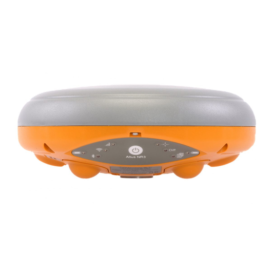
2.3 Altus NR3 design 2.3.1 Front Panel The Altus NR3 has an intuitive front panel with status LEDs and a central power button. Figure 2-2: Altus NR3 Front Panel The table below provides an overview of the LED indicators. A complete description of their... - Page 17 CHAPTER 2. ALTUS NR3 OVERVIEW Function Indication Battery Power level (Green to Red) Battery Power Level solidly lit = battery is in use, blinking = battery is not in use Bluetooth is off (not lit), Bluetooth is on but not discoverable (blue, blinking...
- Page 18 CHAPTER 2. ALTUS NR3 OVERVIEW Power Button Functions As well as turning the Altus NR3 off and on, the front-panel power button can also be used to toggle WiFi and internal logging as described in Table 2.3-2. Table 2.3-2: Altus NR3 power button functions...
-
Page 19: Location Of Batteries And Sim Card
2.3.2 Location of Batteries and SIM card • The Altus NR3 contains two battery bays. The positive contact for the batteries is that nearest to the front label. The SIM card slot is located under the left battery bay and has a watertight cover. -
Page 20: Altus Nr3 Connector
CHAPTER 2. ALTUS NR3 OVERVIEW 2.3.3 Altus NR3 Connector The Altus NR3 has one 9-Pin Lemo connection socket on its underside as shown in Figure 2-5. When connected to the AC Adapter , this will power the device. It is recommended not... -
Page 21: Getting Started With The Altus Nr3
A WiFi or USB connection to a phone, tablet or computer • A WiFi enabled device can be used to configure the Altus NR3 using the Web Interface. • Any device with a USB port can also be used to connect via the Web Interface and configure the Altus NR3. -
Page 22: Setting Up The Altus Nr3
Turn off the Altus NR3 to install or remove the SIM card. Damage to the SIM card may occur if installed or removed while the unit is powered. 1. Place the Altus NR3 on a flat surface with its battery compartments facing up as shown in Figure 2-3 2. -
Page 23: Switching Wifi On/Off
CHAPTER 3. GETTING STARTED WITH THE ALTUS NR3 3.2.4 Switching WiFi on/off The easiest way to configure the Altus NR3 is using the Web Interface over WiFi. 1. If the WiFi radio is already switched on, the WiFi LED will be lit (green) 2. -
Page 24: Connecting To The Web Interface
The Altus NR3 can be fully configured and monitored using the Web Interface. Any WiFi device that supports a web browser can connect to the Altus NR3 via the Web Interface. The Altus NR3 identifies itself as a wireless network or an access point by default. The procedure to connect to the Altus NR3 over WiFi is given in the steps below. -
Page 25: Configuring The Altus Nr3 As A Rover
4 Configuring the Altus NR3 as a rover 4.1 Standard rover receiver settings For the Altus NR3 to operate as a rover and accept differential correction data from a Base station, check that Rover is selected in the ‘Mode’ field of the ‘Position Mode’ window in the ‘GNSS’... - Page 26 CHAPTER 4. CONFIGURING THE ALTUS NR3 AS A ROVER Figure 4-2: With the default ‘auto’ setting, Altus NR3 will accept any format of incoming differential corrections.
-
Page 27: Configuring The Connection To A Base Station
2. Enter a Cellular PIN and Access Point Name (APN) in this window. You may also need to enter a Username and Password. 3. Make sure the ’on’ buttons of both Power and Connect are selected. 4. Click ‘Ok’ Figure 4-3: Connecting the Altus NR3 to the internet using the cellular modem... - Page 28 CHAPTER 4. CONFIGURING THE ALTUS NR3 AS A ROVER If the connection has been established successfully, the Status will follow the sequence: Initializing → Connecting → Connected The connection line in the Cellular field will become green and indicate the connection type (e.g.
-
Page 29: Connection To An Ntrip Caster
CHAPTER 4. CONFIGURING THE ALTUS NR3 AS A ROVER 4.2.2 Connection to an NTRIP Caster Step 1: Configure the NTRIP Client settings 1. Make sure you have a cellular connection as described in the previous section. 2. On the Corrections/NTRIP window, click on New NTRIP client as shown in Figure 4-4 Figure 4-4: NTRIP tab of the Web Interface 3. - Page 30 CHAPTER 4. CONFIGURING THE ALTUS NR3 AS A ROVER Figure 4-6: Receiving differential corrections via NTRIP If the Mode Field is set to ‘Client’, the Altus NR3 will auto-connect to the NTRIP Caster each time it is powered, provided the configuration is saved to boot.
-
Page 31: Connecting Via Data Call
0474 90 86 52. Step 1: Check the receiver is in Rover mode Section 4.1 shows how you can check that the Altus NR3 is set to work as a rover. Step 2: Configure the connection to the base station From the ‘Communication’... - Page 32 CHAPTER 4. CONFIGURING THE ALTUS NR3 AS A ROVER Figure 4-7: Configuring the base station receiver to call the rover receiver using data call Note that the Data Call feature only works when using batteries and will not work when the Altus NR3 is connected to an external power supply.
-
Page 33: Connecting Via An Ip Address Using Mobile Internet
The setup described in this section is represented schematically in Figure 4-8. Figure 4-8: Base-Rover configuration using GSM Step 1: Configure your cellular connection Make sure that the Cell modem of the Altus NR3 is connected to the internet as described in Section 4.2.1. Step 2: Configure the IPR connection Setup an IPR (Receive) connection so the unit can accept the differential corrections via the... - Page 34 CHAPTER 4. CONFIGURING THE ALTUS NR3 AS A ROVER Figure 4-9: Enter the TCP/IP address and port number of the connection Step 3: Configure the input of differential corrections On the ‘Corrections Input’ tab, you can select the communication port and the RTCM stream expected as input as shown in Figure 4-10.
-
Page 35: Connecting Via Wifi
Figure 4-11: Base-Rover configuration using WiFi Step 1: Check the receiver is in Rover mode Section 4.1 shows how you can check that the Altus NR3 is set to work as a rover. Step 2: Configure rover input of differential corrections Configure the rover WiFi connection as Client over USB... - Page 36 CHAPTER 4. CONFIGURING THE ALTUS NR3 AS A ROVER Figure 4-12: Click on ‘Enable WiFi Client’ then ‘Ok’ • Next, click on the ‘Configure Networks’ button in the ‘WiFi Client Status’ panel as shown in Figure 4-13. This will display a list of reachable WiFi networks.
- Page 37 CHAPTER 4. CONFIGURING THE ALTUS NR3 AS A ROVER Configure the input of differential corrections On the ‘Corrections Input’ tab, you can select the format of corrections that will be accepted. The default setting is ‘auto’, as shown in Figure 4-15, which detects the format automatically however, a specific format can be explicitly selected using the drop-down list.
- Page 38 CHAPTER 4. CONFIGURING THE ALTUS NR3 AS A ROVER Step 3: Configure any additional settings Section 4.5 details some additional settings that you may need. Step 4: Verifying the configuration If both the base station and rover receivers have been configured correctly, the rover ‘Overview’...
-
Page 39: Using L-Band Ppp Correction Data With The Altus Nr3
Augmented Data Svc should appear as permitted as shown in Figure 4-18. Figure 4-18: Check that PPP is enabled in the Altus NR3 permission file If you don’t have PPP permissions on your Altus NR3, you can purchase this option from the Septentrio sales department: sales@septentrio.com. - Page 40 SECORX, you will also need to have a SECORX subscription which can be purchased from your Altus NR3 dealer or from the Septentrio sales department: sales@septentrio.com. To activate SECORX you will need to provide the Product Activation Code (PAC) of the receiver.
- Page 41 Figure 4-21: Selecting the L-Band beam Without a SECORX subscription, the Altus NR3 will still be able to track visible L-Band signals. Figure 4-22 shows the L-Band Tracker Status field when the Altus NR3 is locked onto signals from the 25E satellite which transmits at 1545.825 Mz.
- Page 42 CHAPTER 4. CONFIGURING THE ALTUS NR3 AS A ROVER Figure 4-23: L-Band decoder Information field showing that SECORX decoding is enabled...
-
Page 43: Configuring Data Output Over Bluetooth
5. Using your preferred GIS or Survey application on the device make sure you connect to the Bluetooth port created by the Bluetooth manager of your device. Unless there are specific reasons to make the Altus NR3 undiscoverable, it is advised to leave the Discoverable option switched on. -
Page 44: Configuring Output Of Sbf And Nmea Data
CHAPTER 4. CONFIGURING THE ALTUS NR3 AS A ROVER 4.4.2 Configuring output of SBF and NMEA data The Altus NR3 can be configured to output SBF or NMEA data in the ‘NMEA/SBF Output’ window. Select either NMEA or SBF •... -
Page 45: Additional Rover Settings
2. Click ‘Apply’ when finished. In the example shown in Figure 4-26, an offset of 2.0 metres was used. Figure 4-26: GNSS Tab: setting Antenna Offset The Altus NR3 automatically compensates for the Antenna Phase Centre offset using the approved calibration of the product in order to provide the most accurate position out of the box. -
Page 46: Configuring Altus Nr3 As A Base Station
Note that the Data Call feature only works when using batteries and will not work when the Altus NR3 is connected to an external power supply. A summary of the pros and cons of the first three connection methods can be found in Appendix C. - Page 47 CHAPTER 5. CONFIGURING ALTUS NR3 AS A BASE STATION Set the correct position The next step is to set the antenna position of the Altus NR3. The default setting of ‘auto’ can be used for demonstration or for relative positioning however, for most other purposes, a properly surveyed position is advisable.
-
Page 48: Connecting The B
90 86 52. With the ‘Role’ set to ‘Accepting’, any call the receiver will automatically accept any incoming call. Figure 5-3: Overview of the Base-Rover configuration for differential correction transfer over Data Call Step 1: Setting the Altus NR3 base station position Set the Altus NR3 base station position as described in Section 5.1... - Page 49 CHAPTER 5. CONFIGURING ALTUS NR3 AS A BASE STATION Step 2: Configure the connection to the rover From the ‘Communication’ menu select ‘Cellular’, where you can configure the cellular modem of the Base station receiver for the reception of a data call. The essential settings are highlighted in Figure 5-4 with other settings being optional.
- Page 50 CHAPTER 5. CONFIGURING ALTUS NR3 AS A BASE STATION Step 3: Configure output of differential corrections On the Corrections Output window, you can select the type, number and rate of differential corrections that you want to send to the rover receiver. The particular messages necessary for RTK and DGNSS are selected by default.
-
Page 51: Connecting Via Mobile Internet
It is important to remember that with most mobile network providers, the assigned IP address of the cellular modem in the Altus NR3 will be changed every time that a new connection is made. As such the Rover units will... - Page 52 Fixed IP address on your SIM card. If you do not have a Fixed IP address then it is recommended to use the Dynamic DNS service from the Altus NR3 which will allow the Rover receiver to use a fixed and unique URL for connecting to the Base receiver (e.g.
- Page 53 CHAPTER 5. CONFIGURING ALTUS NR3 AS A BASE STATION Configure the correction stream On the Corrections Output window, click on New RTCM3 output as shown in Figure 5-9. You can then select the IPS connection configured in the previous step. The messages...
-
Page 54: Connecting Via Wifi
WiFi access point while the rover is configured as a client. Figure 5-10: Base-Rover configuration using WiFi Step 1: Setting the Altus NR3 base station position Set the Altus NR3 base station position as described in Section 5.1 Step 2: Configure the Base station output of differential corrections Configure your WiFi connection as an Access point... - Page 55 CHAPTER 5. CONFIGURING ALTUS NR3 AS A BASE STATION Figure 5-11: Connecting over USB to the web interface using the URL 192.168.3.1 In the ‘Communication/WiFi’ window ‘AccessPoint’ can then be selected as the WiFi mode as indicated in Figure 5-12.
- Page 56 CHAPTER 5. CONFIGURING ALTUS NR3 AS A BASE STATION Figure 5-13: Select and configure an IP Server port on which to output differential corrections Configure the correction stream On the Corrections Output window, click on New RTCM3 output as shown in Figure 5-9.
- Page 57 CHAPTER 5. CONFIGURING ALTUS NR3 AS A BASE STATION Figure 5-14: Output RTCMv3 diff corr on the configured TCP/IP server port of the base station receiver...
-
Page 58: Nmea Data
6 Other receiver operations 6.1 Logging SBF and NMEA data Data can be logged on the internal 8 GB disk of the Altus NR3 in either SBF (Septentrio Binary Format) and/or NMEA messages (National Marine Electronics Association). Section 6.2 details how to download data logged on the receiver. -
Page 59: Advanced Settings For Logging
CHAPTER 6. OTHER RECEIVER OPERATIONS 6.1.2 Advanced Settings for Logging The ‘Advanced’ tab offers several additional logging options. For Base station use, the ‘Marker and Station Parameters’ fields can be filled in. You can also specify what you want to happen when the internal disk becomes full. -
Page 60: Using The Web Interface
CHAPTER 6. OTHER RECEIVER OPERATIONS 6.2 Downloading logged data from receiver As described in Section 6.1, data can be stored on the internal disk of the receiver. The logged data can be downloaded from the receiver over WiFi using the Web Interface or over USB using the data cable. -
Page 61: Using The Usb Connection
CHAPTER 6. OTHER RECEIVER OPERATIONS 6.2.2 Using the USB connection Connecting the USB data cable for the first time The USB drivers for the Altus NR3 can be installed by following the steps below: Make sure the computer is connected to the internet •... - Page 62 2. Connect the Altus NR3 to a USB port of your computer using the USB communication cable 3. On a Windows computer the Altus NR3 will appear as an extra drive in the file explorer after a few seconds 4. The Altus NR3 appears as a drive named ‘Altus_NR3-xxxxxxx DSK1’ where ‘xxxxxxx’ is the 7-digit serial number of the receiver 5.
- Page 63 CHAPTER 6. OTHER RECEIVER OPERATIONS Connecting via ‘Ethernet over USB’ The web Interface of the Altus NR3 can be accessed over an ‘Ethernet over USB’ connection. If the Altus NR3 has not been connected to the computer being used before then first execute the steps described in the Section 6.2.2.
-
Page 64: Configurations
CHAPTER 6. OTHER RECEIVER OPERATIONS 6.3 Configurations A configuration is a collection of all settings and values that determine the behaviour of the receiver. The table below gives an overview of the Altus NR3’s configurations. Persists after Writable Description Configuration... -
Page 65: Saving The Configuration
CHAPTER 6. OTHER RECEIVER OPERATIONS 6.3.1 Saving the configuration After each change made to the configuration of the Altus NR3, the pop-up shown in Figure 6-6 will appear. Clicking on ‘Save’ will cause the new configuration to be applied the next time the receiver is powered. -
Page 66: Managing Configurations
CHAPTER 6. OTHER RECEIVER OPERATIONS 6.3.2 Managing configurations The Altus NR3’s configurations can be managed from the Admin tab. 1. Click the Admin tab. 2. Select Configurations. The Configurations tab will resemble Figure 6-8. Figure 6-8: Web Interface Admin-Configurations Copy Configuration File 1. -
Page 67: Ynamic Dns
Step 1: Open a Dynamic DNS account To make use of this feature on the Altus NR3, you should first create an account with a Dynamic DNS provider to register a hostname for your receiver. The Altus NR3 supports the following two services: •... -
Page 68: Nr3
CHAPTER 6. OTHER RECEIVER OPERATIONS 6.5 Resetting the Altus NR3 When the Altus NR3 is not operating as expected, a simple reset may resolve matters. The receiver can be reset as shown in Figure 6-10. The reset options are described in Tables 6.5-1 and 6.5-2. - Page 69 CHAPTER 6. OTHER RECEIVER OPERATIONS 6.6 Upgrading the firmware Firmware upgrades for the Altus NR3 are freely available for the lifetime of the receiver and can be downloaded from the Support section of the Septentrio website. All upgrade files and documentation relating to the upgrade are bundled together in a single upgrade zip file.
- Page 70 CHAPTER 6. OTHER RECEIVER OPERATIONS 6.7 How to manage access to the Altus NR3 You can manage the access that users have to the Altus NR3 in the User Administration window of the Admin menu. By default, all communication interfaces are assigned User-level access except the DataCall port as shown in Figure 6-13.
- Page 71 After defining the Users/Viewers and their access levels, they can then login on the web interface by clicking on Log in on the upper-right corner as shown in Figure 6-15. Figure 6-15: Logging in to the Altus NR3 web interface...
-
Page 72: Ssh Key Authentication
By default, anonymous users have full access over FTP, SFTP and rsync to the files logged on the Altus NR3. FTP, SFTP and rsync access can be limited by configuring user access, as described in Section 6.7. For added security, user authentication for SFTP and rsync access can be configured using an SSH public key. -
Page 73: Onsole
CHAPTER 6. OTHER RECEIVER OPERATIONS 6.8 Using the Expert Console Commands can be sent to the Altus NR3 using the Expert Console window on the accessible via the Admin menu as shown in Figure 6-18 • The drop-down box showing ‘Mainboard (Altus NR3)’ allows selecting which of the Altus NR3’s sub-systems to direct the command. -
Page 74: Support Sbf File
6.9 How to log data for problem diagnosis If the Altus NR3 does not behave as expected and you need to contact Septentrio Support Department, it is often useful to send a short SBF data file that captures the anomalous behaviour, as well as a Diagnostic Report. - Page 75 CHAPTER 6. OTHER RECEIVER OPERATIONS Figure 6-20: Configure a logging session selecting Support in the Edit SBF Stream field Figure 6-21: Selecting BBSamples in the Edit SBF Stream field for logging interference Please note that logging the Support data blocks requires a large throughput of data that may not be compatible with other CPU-intensive tasks such as data output at higher rates.
- Page 76 CHAPTER 6. OTHER RECEIVER OPERATIONS Step 3: Downloading the logged SBF file To download a data file logged on the Altus NR3, click on Disk Contents or on the pie chart in the ’Disk Usage’ box and then click the download icon next to the filename on the Disk...
-
Page 77: Diagnostic Report
A Diagnostic Report can be generated under the Admin/About tab on the Web interface as shown in Figure 6-24 and saved to your PC. Note that the About menu also contains information on the Altus NR3’s hardware and software components in the Receiver Identification field. -
Page 78: Gis Collection With Pinpoint-Gis Or Other Applications 7.1 Introduction
PinPoint-GIS App. PinPoint-GIS Web PinPoint-GIS Web is an extension of Septentrio’s web interface with a direct link to ArcGIS Online. It offers a unique solution with the power to run GIS collection inside Septentrio GNSS receivers. No extra applications are needed, simply use your preferred web browser for full GIS workflow - from accurate data collection in the field directly to the ArcGIS Online... - Page 79 The following sections provide an introduction to using PinPoint-GIS Web and PinPoint-GIS App. An additional section provides details on the newer version of Collector for ArcGIS with the Altus NR3. A glossary of the terms that are used in these sections can be found in Appendix E.
-
Page 80: Designing A Collection Project
CHAPTER 7. GIS COLLECTION WITH PINPOINT-GIS OR OTHER APPLICATIONS 7.2 Using the Altus NR3 on-board simple data collector 7.2.1 Designing a collection project On the PinPoint-GIS page of the Web Interface, click on PinPoint-GIS Rx to select and edit a collection project. There are three collection projects that can be configured. Select the... - Page 81 CHAPTER 7. GIS COLLECTION WITH PINPOINT-GIS OR OTHER APPLICATIONS Adding a user-defined attribute On the project pop-up, click New attribute then select User to define a user-defined attribute. Fill in the name of the attribute and default value you want it to take. Adding a receiver output attribute Again click on New attribute then select Receiver.
-
Page 82: Performing A Collection
CHAPTER 7. GIS COLLECTION WITH PINPOINT-GIS OR OTHER APPLICATIONS 7.2.2 Performing a collection On the PinPoint-GIS window, click on PinPoint-GIS Rx and then the Manage button next to the project you want to use. You can then click on the Collector button to start a collection. At each collection point, click on collect and enter the details of the user-defined attribute then click Save. -
Page 83: Downloading Collected Data
CHAPTER 7. GIS COLLECTION WITH PINPOINT-GIS OR OTHER APPLICATIONS 7.2.3 Downloading collected data On the PinPoint-GIS window, click on PinPoint-GIS Rx and then the Manage button next to the project you want download. The project window will pop-up where you can click on the CSV Export button. -
Page 84: Creating A Map
CHAPTER 7. GIS COLLECTION WITH PINPOINT-GIS OR OTHER APPLICATIONS 7.3 Creating a map To be able to use PinPoint-GIS Web or Collector for ArcGIS you will need an ArcGIS Online account. ArcGIS accounts are either public (free) or commercial (payable). Public accounts allow you to create your own maps using feature layers which are publicly available on the internet. - Page 85 CHAPTER 7. GIS COLLECTION WITH PINPOINT-GIS OR OTHER APPLICATIONS 3-Prepare your map You can add different layers to your map • • Layers can be either collectable or non-collectable (e.g. a traffic layer is not collectable while a manhole inspection layer will have some collection possibilities) Add Layers by clicking on ‘...
- Page 86 Altus NR3 (using the URL: http://192.168.20.1). • Make sure the GSM of the Altus NR3 is on and connected to the internet. You can configure the cellular modem on the Communication/ cellular tab on the web interface.
- Page 87 CHAPTER 7. GIS COLLECTION WITH PINPOINT-GIS OR OTHER APPLICATIONS 7.5 Using PinPoint-GIS Web PinPoint-GIS Web allows you to either access your ArcGIS Online maps or to perform data collection which is synchronized directly with Esri ArcGIS Online (it is a cross-platform alternative to using Collector for ArcGIS.
- Page 88 CHAPTER 7. GIS COLLECTION WITH PINPOINT-GIS OR OTHER APPLICATIONS Figure 7-9: Functions within PinPoint-GIS Web Access your maps from the Altus NR3 • Connect to your Altus NR3 receiver Go to the GNSS/PinPoint-GIS Web tab where you • should see a basic map Your browser should be connected to the internet (See Section 7.4).
-
Page 89: Optional: Auto Filling Of Gnss Attributes
More information about all the fields of SBF blocks can be found at the Reference guide of the Altus NR3. It is also possible within the web interface to check the Message inspector located in the Expert Console menu so that you can visualize the fields which could be filled. - Page 90 CHAPTER 7. GIS COLLECTION WITH PINPOINT-GIS OR OTHER APPLICATIONS Table 7.5-4: Type conversion for auto filled GNSS attributes To be able to add extra attributes to a GIS database you will need to use either ArcGIS Online or ArcGIS PRO Desktop SW. The steps below explain how to prepare a map for auto filling of GNSS data using ArcGIS Online.
- Page 91 5. Once you have added the field, please make sure you save your map. 6. Once saved, when you add a collection in ArcGIS Online you will see the form field automatically filled by the Altus NR3 Figure 7-12: Auto-filled values in PinPoint-GIS Web Note that even if not the whole accuracy is shown in the form auto filled values, PinPoint-GIS...
-
Page 92: Gis App
With the PinPoint-GIS App, you can choose to use either the internal cellular connection of the Altus NR3, or the connection of your mobile device. The diagrams above show schematically the connection options. The PinPoint-GIS App is an application which can be used along with any other Android applications. - Page 93 • In the App Settings menu of the app you can find the Location Overriding option. Note that when you override the internal GPS • position, other applications running on your device will now also use the Altus NR3 position.
- Page 94 Keep PinPoint-GIS running in the background (by clicking the home key in your Android device) and open your preferred Android GIS application The current location of the Altus NR3 will be used • in your own app (if location overriding has been...
-
Page 95: Nr3
Collector for ArcGIS is an application which allows GIS data collection into ArcGIS Online. The latest version of Collector for ArcGIS offers compatibility with the Altus NR3 receiver. This allows customers working within the Esri environment to perform high-accuracy data collection straight into the ArcGIS Online cloud. - Page 96 Tap Add to add the receiver to the location provider list and switch to using the Altus NR3. Differential Corrections can be received either using the Altus NR3 Cellular modem or by using the PinPoint-GIS App. If the PinPoint-GIS App is used then it is recommended to use a WiFi connection for the PinPoint-GIS App connection so that Bluetooth port can be used for the Collector app.
- Page 97 CHAPTER 7. GIS COLLECTION WITH PINPOINT-GIS OR OTHER APPLICATIONS 4-Create a Location Profile • In the Settings of Collector, under Location, select Location Profile and select Add Profile ‘+’. • Browse for the Geographic or Projected coordinate system of the map’s coordinate system.
-
Page 98: Web Interface
A Status icons and front-panel LEDs A.1 Status Icons on the Web Interface The icons on the right hand side of the top banner quickly show the user the status of the Altus NR3. Table A.1-1: Web Interface Status Icons... -
Page 99: Appendix A Status Icons And Front-Panel Leds A.1 Status Icons On The A.2 Front Panel Led S
APPENDIX A. STATUS ICONS AND FRONT-PANEL LEDS A.2 Front Panel LEDs Table A.2-1: Front-panel LED behaviour... -
Page 100: Appendix B Batteries B.1 Charging
B.1.2 Using the AC adapter The batteries of the Altus NR3 can be charged inside the device while it is connected to an external power supply . Battery charging will stop if the Altus NR3 is switched off or if the temperature inside the device goes below 0Âř... -
Page 101: Nr3
Figure B-1: The red dot on the lemo plug should align with the centre of the Altus B.2 Hot Swapping the batteries and charging When both batteries are below 5% then the Altus NR3 will make use of both batteries. The user may replace either battery without interrupting operation. - Page 102 APPENDIX C. POINT-TO-POINT CONNECTIONS C Point-to-Point connections Two Altus NR3 units configured as a Base station and rover, can be connected to each other in order to transfer differential corrections over the connections listed in the Table below. Range and...
- Page 103 • Make sure your mobile device has been configured with personal hotspot (a user and a password will be displayed to the user) • Configure the Altus NR3 in WiFi Client mode so that it can connect to your mobile device (using the credentials from the mobile device) •...
- Page 104 APPENDIX E. GLOSSARY OF ARCGIS AND PINPOINT-GIS TERMS E Glossary of ArcGIS and PinPoint-GIS terms ◦ A geographic information system (GIS) describes any information system that can integrate, store, edit, analyse, share, and display geographic information. applications allow users to analyse spatial information, edit data in maps and present the results of these operations ArcGIS Online ◦...
- Page 105 APPENDIX F. LIST OF TYPICAL GNSS RELATED ACRONYMS F List of Typical GNSS Related Acronyms A Posteriori Multipath Estimation APME Antenna Reference Point ASCII American Standard Code for Information Interchange Compact Measurement Record Central Processing Unit Carriage Return Clear to Send Differential Global Positioning System DGPS Dilution of Precision...
Need help?
Do you have a question about the Altus NR3 and is the answer not in the manual?
Questions and answers