Table of Contents
Advertisement
Advertisement
Table of Contents

Related Manuals for AirClean systems PowderSafe AC730C

Summary of Contents for AirClean systems PowderSafe AC730C
- Page 1 OPERATOR’S MANUAL Type B Ductless Balance Enclosure Models: AC730C AC740C...
-
Page 2: Table Of Contents
TABLE OF CONTENTS SECTION PAGE Declaration of Conformity Symbols & Definitions Cautions and Precautions Specifications Product Overview Airflow Diagram Unpacking and Installation 9-11 Controller Instructions 12-14 Operating Instructions Prefilter Main Filter(s) Filter Serial # Instructions Fluorescent Bulbs Cleaning Spare Parts Cart Assembly 28-29 Warranty... -
Page 3: Declaration Of Conformity
DECLARATION OF CONFORMITY AirClean Systems, Inc. ® 3248 Lake Woodard Drive Raleigh, North Carolina 27604 declare that: Product Name: PowderSafe Type B Model Numbers: AC730C, AC740C in accordance with the following Directives: 73/23/EEC The Low Voltage Directive as amended by 93/68/EEC 89/336/EEC EMC Directive as amended by 92/31/EEC has been designed and manufactured to the following specifications:... -
Page 4: Symbols & Definitions
SYMBOLS AND DEFINITIONS The lightning flash with arrowhead symbol within an equilateral triangle alerts the user to the presence of dangerous voltages within the product’s enclosure that maybe of sufficient magnitude to constitute a risk of electric shock to persons. The exclamation point within an equilateral triangle alerts the user to the presence of important operating maintenance or service instructions. -
Page 5: Cautions And Precautions
CAUTIONS AND PRECAUTIONS Signal Words and Meanings WARNING - Indicates a potentially hazardous situation, which if not avoided, could result in death or serious injury. CAUTION - indicates a potentially hazardous situation, which if not avoided, may result in minor or moderate injury. It may also be used to alert against unsafe practices or potential equipment damage. -
Page 6: Specifications
TECHNICAL SPECIFICATIONS SPECIFICATIONS AC730C AC740C Physical Dimensions Outside Dimensions 32”w x 33”h x 30”d 48”w x 33”h x 30”d Inside Dimensions 31”w x 20”h x 22”d 47”w x 20”h x 22”d Weight Filters included 150 lbs. 250 lbs. Airflow Characteristics Low Airflow Alarm Audible/Visible Audible/Visible Volume of Filtered Air... -
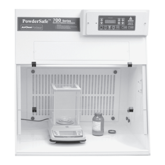
Page 7: Product Overview
OVERVIEW Type B Enclosure AirClean Systems Type B enclosures provide maximum operator protection during weighing ® and filter change out. Variable Airflow Volume Control ensures constant operator protection from exposure to pharmaceutical compounds. AirClean Systems HEPASafe™ filter change technology allows for safe and easy change ®... -
Page 8: Airflow Diagram
AIRFLOW DIAGRAM Figure 1. Airflow diagram How PowderSafe™ Type B Works: 1. Air enters at “A” and is drawn in a laminar flow toward the rear plenum of the enclosure while being mixed with contaminated air ”B”. 2. At “C” the contaminated air first enters a roughing pre-filter before entering the primary HEPA filter. -
Page 9: Unpacking And Installation
UNPACKING AND INSTALLATION INSTRUCTIONS 1) Make sure that your workstation arrived secured to a pallet/skid. Inspect the exterior packaging (box) for damage. Note any damage or absence of pallet on the freight carrier’s waybill and call AirClean Systems immediately. ® 2) Put on safety glasses and cut banding material. - Page 10 Sash Hinges Figure 3. Lifting the workstation properly. 8) Place the workstation in the desired location. Once in place, make sure that it is secure and stable. 9) Visually inspect your workstation, checking for any damage that may have occurred in shipping.
- Page 11 CAUTION: Only use approved accessories with the exterior connectors. 13) Make sure that any exterior linecord connections are secure and seated properly. These connections are located on the back right side of the workstation. See figure 5. 14) Locate the power entry module on the right side of the workstation. Insert the female end of the linecord into the power entry module and the male end into an appro- prate electrical outlet.
-
Page 12: Controller Instructions
CONTROLLER INSTRUCTIONS PROGRAMMING MODE SELECT MODEL 300 CONTROLLER QUICK KEYS ALARM POWER BLOWER TIMER PUMP LIGHT Figure 6. AirSafe automatic safety controller layout. ™ QUICK KEYS BLOWER - Default screen will continuously display face velocity while blower is activated. PUMP - Inactive key for enclosure. LIGHT - One touch to enable fluorescent light. - Page 13 PROGRAMMING KEYS The AirSafe Automatic Safety Controller is the first of its kind on the market. This ™ breakthrough was designed to give the user a variety of options with the ease of fingertip control. The keypad consists of 13 keys, each with a specific function: Allows the operator to move between MODE different program screens.
- Page 14 PROGRAMMING MENUS BLOWER CONTROL – This menu is preset at the factory to meet O.S.H.A. face velocity standards while in AUTOMATIC mode. From this screen you can: • Turn the blower on/off. • Switch from automatic to manual blower speed based on the application. •...
-
Page 15: Operating Instructions
OPERATING INSTRUCTIONS The following operating instructions are specific for using powders and particulate in your AirClean Systems PowderSafe enclosure. ® ™ NOTE: Ensure that the INSTALLATION AND ASSEMBLY INSTRUCTION steps have been completed. A. To operate the PowderSafe enclosure: ™ 1. -
Page 16: Prefilter
MAINTENANCE Pre-filters Pre-filters should be checked each month. In most cases, they should be changed every 1 to 3 months. Prefilter replacement is required when discoloration of the prefilter occurs or when the low airflow alarm comes on. See the “PRE-FILTER CHECK/REPLACEMENT” section of this manual for complete instructions. - Page 17 4. Remove the 4 black knobs or turn the 6 polypropylene clips that hold the prefilter grid in place. This will expose the clogged pre-filter. Do not remove the pre-filter from the hood! Figure 8. AC740C Pre-filter clips. Figure 9. AC740C Pre-filter and HEPA filter. 5. Remove the pre-filter from the pre-filter grid and place it inside the poly bag. Wipe any residue off of the pre-filter grid and base of the enclosure.
-
Page 18: Main Filter(S)
MAINTENANCE FILTER REPLACEMENT CAUTION: Disconnect the linecord from the power entry module prior to proceeding. HEPA Filters The HEPA filter must be changed atlease every two years. See the “FILTER REPLACEMENT” section of this manual for complete instructions. The HEPA filter must be changed every two years or whenever it is clogged. The frequency with which the filter must be changed depends upon usage. - Page 19 4. Remove the pre-filter from the pre-filter grid and place it inside the poly bag. Wipe any residue off of the pre-filter grid and base of the workstation. Place the rag inside the bag with the pre- filter and seal the bag. Figure 11. AC740C Pre-filter and HEPA filter.
-
Page 20: Filter Serial # Instructions
MAINTENANCE B. To install the new ACFHEPA filter: 1. Remove the ACFHEPA from the packaging. Visually inspect the HEPA filter for rips in the filter media. 2. Place the filter into the filter grid with the gasket and screen side facing away from you. 3. Place the filter hold down frame over the HEPA filter and secure it with the hex nuts. 4. -
Page 21: Fluorescent Bulbs
BULBS CAUTION: Disconnect the linecord from the power entry module prior to proceeding. Fluorescent Light Bulb Replacement -AC730: 1. Remove the linecord from the power entry module as shown in figure 5. 2. Using a flat head screwdriver, remove the two bolts holding the light cover in place. - Page 22 CAUTION: Disconnect the linecord from the power entry module prior to proceeding. Fluorescent Light Bulb Replacement -AC740: 1. Remove the linecord from the power entry module as shown in figure 5. 2. Using a philips head screwdriver, remove the two mounting screws that hold the light tray in place, located on the right side of the enclosure.
- Page 23 5. Pull the light tray out until you can remove the bulb. 6. Grasp the bulb with both hands and turn 1/4 turn counter-clockwise to release. Gently pull down on the bulb, remove it from the fixture and discard. 7. Install the new bulb by sliding into the light socket and turning clockwise 1/4 turn until it locks into place.
- Page 24 CONTROLLER WARNING: Only remove the controller module under the direction of an AirClean Systems trained ® technician. Controller Replacement for AC730/AC740C Model Workstation Removal 1. Remove the linecord from the power entry module as shown in figure 5. WARNING: If the linecord has not been removed there may be potentially hazardous voltages present behind the controller module.
- Page 25 Replacement WARNING: If the linecord has not been removed there may be potentially hazardous voltages present behind the controller module. 4. Place the new control module so that the left rear corner is in the control box opening. 5. Reattach the two connectors at the rear of the control box. 6.
-
Page 26: Cleaning
CLEANING Follow the recommended guidelines below for safe cleaning procedures. 1. Any cleaning solution can be used on the white polypropylene structure since it is impervious to most chemicals and certainly impervious to all common cleaning chemicals. 2. The sash should always be cleaned with an acrylic foam cleaner or a soft damp cloth. -
Page 27: Spare Parts
SPARE PARTS LIST CATALOG NO. DESCRIPTION AC730C AC740C 12-52181 Airflow Rubber Gasket 10-50738 Airflow Sensor 10-50267 Blower/Fan 10-50271 Blower/Fan 10-50928 Capacitor 10-50608 Capacitor 10-51579 Electronics Box 12-52184 Filter Hatch Cover Assembly 12-52183 Filter Hatch Cover Assembly 10-50428 Fuse 6.3A Slo-Blo ®... -
Page 28: Cart Assembly
OPTIONS Cart Instructions LEAN YSTEMS SSEMBLY NSTRUCTIONS ® Model ACA1029 and ACA1041 Your AirClean Systems Cart is shipped with the following components: ® 4 – Cross pieces 2 – End pieces 4 – 3/8” washers (hood bolt washers) 8 – 2 ¼” x ¼” Phillips head bolts (cross piece bolts) 8 –... - Page 29 CART COMPONENTS Mounting Holes 4 - ⅜” Washer 8 - 1¼” Washer Hole 1 Hole 2 Hole 3 Hole 4 4 - 1¾” x ¼” Bolt 8 - 2” x ¼” Bolt Hole 5 4 - Cart Cross Piece BOTTOM 2 - Cart End Piece 2 - Standard Caster 2 - Locking Caster ASSEMBLED CART CONFIGURATIONS...
-
Page 30: Warranty
WARRANTY AirClean Systems is committed to providing our customers with quality equipment and ® service after the sale. We, therefore, request that you take a moment to fill out the Warranty Registration Card so that we may know your location as well as some of the reasons that prompted you to purchase our product. -
Page 31: Shipping Claims
SHIPPING CLAIMS If a shipment is received with visible damage, be certain to make a notation on the delivering carrier’s receipt and have their agent confirm the damage on your receipt. Otherwise, the damage claim may be refused. If concealed damage or pilferage is discovered, notify the carrier immediately and retain the entire shipment intact for inspection. -
Page 32: Contact Info
CONTACT INFORMATION If you have any questions that are not addressed in this manual, or if you need technical assistance, please contact AirClean Systems at 919-255-3220 or 800-849-0472 ® Monday-Friday 8:00 AM-5:00 PM EST. AirClean Systems mailing address: ® AirClean Systems ®...
Need help?
Do you have a question about the PowderSafe AC730C and is the answer not in the manual?
Questions and answers