Table of Contents
Advertisement
Quick Links
ASSEMBLY AND CARE INSTRUCTIONS
VERSION: 8920054 (Revised 02/2018)
Canada and International
135 Forestview Road, Oro-Medonte
Ontario, Canada L3V 0R4
Toll-Free:
Telephone: (705) 325-2274
Fax:
service.ca@spiethamerica.com
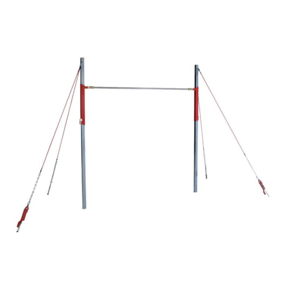
ADJUSTABLE SINGLE BAR TRAINER
WITH SHORT CABLES
SALES AND SERVICE
spiethamerica.com
(800) 563-6479
(705) 325-1485
5176-010
Toll-Free:
Telephone: (517) 999-8230
Fax:
service.usa@spiethamerica.com
USA
3327 Ranger Road
Lansing, MI 48906
(800) 331-8068
(517) 999-8245
Advertisement
Table of Contents

Related Manuals for SPIETH America 5176-010


Summary of Contents for SPIETH America 5176-010
- Page 1 ASSEMBLY AND CARE INSTRUCTIONS ADJUSTABLE SINGLE BAR TRAINER WITH SHORT CABLES 5176-010 VERSION: 8920054 (Revised 02/2018) SALES AND SERVICE spiethamerica.com Canada and International 135 Forestview Road, Oro-Medonte 3327 Ranger Road Ontario, Canada L3V 0R4 Lansing, MI 48906 Toll-Free: (800) 563-6479...
- Page 2 5176-010 ADJUSTABLE SINGLE BAR TRAINER Assembly Instructions Thank you for purchasing a SPIETH America 5176-010 – Adjustable Single Bar Trainer with Short Cables from our line of Gymnastics Equipment. We appreciate your business and value you as a customer! Please carefully read the following instructions before assembling and using your new equipment, as they pertain to the particular equipment you have purchased.
-
Page 3: General Information
Assembly Instructions I. General information 1. Weight of the apparatus Reference 5176-010 weights approximately 119 lbs 2. Overall size Apparatus without cables: 8'-7 9/16" X 4" (2.63 m x 0.10 m) With short cables: 13'-1 7/16" X 6'-6 3/4" (4.00 m x 2.00 m) 3. -
Page 4: Assembly And Operation
4 Concrete Floor anchors are required for securing the Threaded Socket Adaptors. These floor anchors are not supplied with this package. They must be purchased separately. Concrete anchors are available at SPIETH America under spare part #PEA1 (Set of 4 pieces). - Page 5 5176-010 ADJUSTABLE SINGLE BAR TRAINER Assembly Instructions Layout 1. Choose a location for the apparatus and mark the location of the anchors and the distance between the pivots (5) on the floor, according to Figure 2 below. 2. Before drilling measure the diagonal distances between the corners of the layout, to check that the anchors will be uniformly located.
- Page 6 5176-010 ADJUSTABLE SINGLE BAR TRAINER Assembly Instructions 1.2. Installing Concrete Anchors Tools Required (customer supplied): Tape measure Anchor setting tool or punch with a ” diameter & 1.5” long end ” diameter carbide tipped concrete drill bit ...
- Page 7 5176-010 ADJUSTABLE SINGLE BAR TRAINER Assembly Instructions 2. Assembling the apparatus 2.1 Bill of materials Item Description Reference Notes GN3120/60 Uprights for Adjustable single bar Replacement sold by the pair Slide Tubes GN3120/70 Replacement sold by the pair GN3110 Replacement rail sold by the unit...
- Page 8 5176-010 ADJUSTABLE SINGLE BAR TRAINER Assembly Instructions 2.2 Apparatus Assembly Figure 3 Prepare a clean area to assemble the apparatus. The assembly and set-up of the apparatus requires a minimum of two qualified persons. Do not attempt the assembly and set-up of this apparatus alone! 1.
-
Page 9: Installing The Cables
5176-010 ADJUSTABLE SINGLE BAR TRAINER Assembly Instructions 3. Installing the cables 3.1 Bill of materials Item Description Reference Notes Replacement sold by the unit Adjustable Bar turnbuckle cable Replacement sold by the unit Adjustable Bar tightener cable Replacement sold by the unit... - Page 10 5176-010 ADJUSTABLE SINGLE BAR TRAINER Assembly Instructions 1. Make sure you assemble the quick links (3) in the proper direction (always tighten downward) like Figure 7 below. 2. Adjust the turnbuckles (8) to medium length to enable the cables to be adjusted easily like Figure 10 below.
- Page 11 5176-010 ADJUSTABLE SINGLE BAR TRAINER Assembly Instructions When the vertical position of the uprights (1) is adjusted and before tightening the cables, do not forget to tighten the bracing flats (on top of uprights). (See Figure 3 on page 8).
- Page 12 5176-010 ADJUSTABLE SINGLE BAR TRAINER Assembly Instructions 4 Apparatus operation 4.1 Height adjustment Figure 14 1. Loosen the cables by opening the load binders (see Figure 13 on previous page). 2. Unlock the slides tubes by loosening the tightening knobs (4) (2 to 3 turns) on both of the slide tubes (2).
- Page 13 5176-010 ADJUSTABLE SINGLE BAR TRAINER Assembly Instructions 4.2 Maintenance 1. A regular cleaning of the apparatus allows better noticing of eventual issues (distortion, breakage, or corrosion). 2. Before using the apparatus, always check the state of wear parts and safety elements for good condition and operation: ...
- Page 14 5176-010 ADJUSTABLE SINGLE BAR TRAINER Assembly Instructions III. SAFETY WARNING Any activity involving motion or height creates the possibility of serious injury including permanent paralysis and even death, from landing or falling on the neck, head, or other parts of the body.
Need help?
Do you have a question about the 5176-010 and is the answer not in the manual?
Questions and answers