Table of Contents
Advertisement
Quick Links
ASSEMBLY AND CARE INSTRUCTIONS
COMPETITION CRANK BALANCE BEAM
VERSION: 8920028 (Revised 09/17)
Canada and International
135 Forestview Road
Oro-Medonte, Ontario, Canada L3V 0R4
Toll-Free:
Telephone: (705) 325-2274
Fax:
service.ca@spiethamerica.com
5121-120 (16') & 5121-335 (12')
SALES AND SERVICE
spiethamerica.com
(800) 563-6479
(705) 325-1485
USA
3327 Ranger Road
Lansing, MI 48906
Toll-Free:
(800) 331-8068
Telephone: (517) 999-8230
Fax:
(517) 999-8245
service.usa@spiethamerica.com
Advertisement
Table of Contents

Related Manuals for SPIETH America 5121-120


Summary of Contents for SPIETH America 5121-120
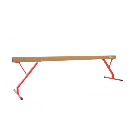
- Page 1 ASSEMBLY AND CARE INSTRUCTIONS COMPETITION CRANK BALANCE BEAM 5121-120 (16’) & 5121-335 (12’) VERSION: 8920028 (Revised 09/17) SALES AND SERVICE spiethamerica.com Canada and International 135 Forestview Road 3327 Ranger Road Oro-Medonte, Ontario, Canada L3V 0R4 Lansing, MI 48906 Toll-Free: (800) 563-6479...
- Page 2 COMPETITION CRANK BALANCE BEAM Assembly Instructions This equipment is manufactured from the finest materials and has been thoroughly inspected before leaving our plant. We are sure you will be pleased with its quality, durability and performance. Please carefully read the following instructions before assembling and using your new equipment. The exclamation mark symbol when seen in this manual is used to indicate warnings or items that require special attention during the use or assembly of the apparatus.
- Page 3 COMPETITION CRANK BALANCE BEAM Assembly Instructions 1. Assembly and adjustment instructions Please note that the Beam Legs and Beam Top are heavy and can be difficult to balance if not held properly during handling. Two (2) qualified persons are required when assembling this apparatus.
- Page 4 COMPETITION CRANK BALANCE BEAM Assembly Instructions 4. Remove both Axle Pins (#6 & 7) from the Adjustable Guide Plate (#4) and the Stationary Guide Plate (#5) at one end of the Beam Top. Remove one screw/bolt and pull/tap the pin out. Watch not to damage the threads.
- Page 5 COMPETITION CRANK BALANCE BEAM Assembly Instructions 1.2. Height Adjustment You are now ready to adjust the height of your new Crank Balance Beam. It is imperative that fingers be kept well clear of the beam channel at all times during height adjustment.
- Page 6 COMPETITION CRANK BALANCE BEAM Assembly Instructions 2. Beam maintenance 2.1. General maintenance At every use, check all welds, axle bolts and foot cups for signs of wear and tear. Check the top surface of the beam as well. Do not perform on the beam until these inspections have occurred and have been approved.
- Page 7 115A Set of 4 – Rubber Foot Cups PEKY-014A 1 Pair – Brace bars c/w hardware and pins P111-14PR 3.2. 5121-120 & 5121-335 Crank Balance Beam replacement parts Description Part Number 1 Piece – Crank Handle P113-39PR 1 Pair – Adjustable Guide Plates for Crank...
- Page 8 COMPETITION CRANK BALANCE BEAM Assembly Instructions 4. SAFETY WARNING Any activity involving motion or height creates the possibility of serious injury including permanent paralysis and even death, from landing or falling on the neck, head, or other parts of the body. You assume a risk of serious injury in using this equipment.
Need help?
Do you have a question about the 5121-120 and is the answer not in the manual?
Questions and answers