Carrier 50JS Installation, Start-Up And Service Instructions Manual
Single-package heat pump units
Hide thumbs
Also See for 50JS:
- User manual (4 pages) ,
- Operating and maintaining manual (4 pages) ,
- Manual to operating and maintaining (12 pages)
Table of Contents
Advertisement
Visit www.carrier.com
Installation, Start-Up and Service Instructions
SAFETY CONSIDERATIONS ...............................................1-4
.................................................................................
RECEIVING AND INSTALLATION..................................4-15
Check Equipment......................................................................4-5
Identify Unit..............................................................................4
Inspect Shipment.......................................................................5
Provide Unit Support...................................................................5
Roof Curb..................................................................................5
Slab Mount................................................................................5
Ground Mount...........................................................................5
Provide Clearances.......................................................................5
Rig and Place Unit....................................................................5-6
Select and Install Ductwork ....................................................6-8
Discharge...................................................................................6
Provide for Condensate Disposal ............................................6-8
Install Electrical Connections .....................................................8
High-Voltage Connections........................................................8
Routing Power Leads Into Unit ..........................................8-14
Connecting Ground Lead to Ground Lug..............................14
Special Procedures for 208-V Operation ...............................15
PRE-START-UP.........................................................................15
START-UP.............................................................................15-20
Check for Refrigerant Leaks ..................................................15
Unit Start-Up Adjustment .................................................15-20
MAINTENANCE ..................................................................20-23
SYSTEM INFORMATION.......................................................23
Time Delay Relay...................................................................23
Pressure Switches....................................................................23
Defrost Thermostat .................................................................23
TROUBLESHOOTING .......................................................24-25
START-UP CHECKLIST .........................................................25
NOTE TO INSTALLER - READ THESE INSTRUCTIONS
CAREFULLY AND COMPLETELY before installing this unit.
Also, make sure the Owner's Manual and Service Instructions are
left with the unit after installation.
SAFETY CONSIDERATIONS
Installation and servicing of air-conditioning equipment can be
hazardous due to system pressure and electrical components. Only
trained and qualified personnel should install, repair, or service
air-conditioning equipment.
Untrained personnel can perform basic maintenance functions of
cleaning coils and filters. All other operations should be performed
by trained service personnel. When working on air-conditioning
equipment, observe precautions in the literature, tags and labels
attached to the unit, and other safety precautions that may apply.
Follow all safety codes. Wear safety glasses and work gloves. Use
quenching cloth for unbrazing operations. Have fire extinguisher
available for all brazing operations.
Manufacturer reserves the right to discontinue, or change at any time, specifications or designs without notice and without incurring obligations.
Book 1 4
PC 101
Catalog No. 565-057
Tab 5a 5a
Single-Package Heat Pump Units
4
Improper installation, adjustment, alteration, service, mainte-
nance, or use can cause explosion, fire, electric shock, or
other occurrences, which could cause serious injury or death
or damage your property. Consult a qualified installer or
service agency for information or assistance. The qualified
installer or agency must use only factory-authorized kits or
accessories when modifying this product.
Recognize safety information. This is the safety-alert symbol
When you see this symbol on the product or in instructions or
manuals, be alert to the potential for personal injury.
Understand the signal words - DANGER, WARNING, CAU-
TION, and NOTE. Danger identifies the most serious hazards,
which will result in severe personal injury or death. Warning
indicates a condition that could cause serious personal injury or
death. Caution is used to identify unsafe practices, which would
result in minor personal injury or product and property damage.
NOTE is used to highlight suggestions which will result in
enhanced installation, reliability or operation.
1. The power supply (volts, phase, and hertz) must correspond to
that specified on unit rating plate.
2. The electrical supply provided by the utility must be sufficient
to handle load imposed by this unit.
3. This installation must conform with local building codes and
with NEC (National Electrical Code). Refer to provincial and
local plumbing or waste water codes and other applicable local
codes.
Printed in U.S.A.
Form 50JS,JX-1SI
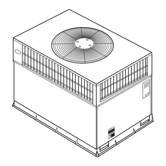
50JS,JX018-060
Fig. 1-Model 50JS/JX
Pg 1
5-00
Replaces: 50JX-2SI
C99001
.
Advertisement
Table of Contents
Troubleshooting

Related Manuals for Carrier 50JS


Summary of Contents for Carrier 50JS
-
Page 1: Table Of Contents
PC 101 Catalog No. 565-057 Tab 5a 5a Single-Package Heat Pump Units Fig. 1—Model 50JS/JX Improper installation, adjustment, alteration, service, mainte- nance, or use can cause explosion, fire, electric shock, or other occurrences, which could cause serious injury or death or damage your property. - Page 2 REQUIRED CLEARANCE TO COMBUSTIBLE MATL. TOP OF UNIT...14.00 [355.6] DUCT SIDE OF UNIT...2.00 [50.8] SIDE OPPOSITE DUCTS ...14.00 [355.6] BOTTOM OF UNIT ...0.50 [12.7] ELECTRIC HEAT PANEL ...36.00 [914.4] NEC. REQUIRED CLEARANCES. BETWEEN UNITS, POWER ENTRY SIDE ...42.00 [1066.8] UNIT AND UNGROUNDED SURFACES, POWER ENTRY SIDE .36.00 [914.0] UNIT AND BLOCK OR CONCRETE WALLS AND OTHER GROUNDED SURFACES, POWER ENTRY SIDE...42.00 [1066.8] UNIT...
- Page 3 REQUIRED CLEARANCE TO COMBUSTIBLE MATL. TOP OF UNIT...14.00 [355.6] DUCT SIDE OF UNIT...2.00 [50.8] SIDE OPPOSITE DUCTS ...14.00 [355.6] BOTTOM OF UNIT ...0.50 [12.7] ELECTRIC HEAT PANEL ...36.00 [914.4] NEC. REQUIRED CLEARANCES. BETWEEN UNITS, POWER ENTRY SIDE ...42.00 [1066.8] UNIT AND UNGROUNDED SURFACES, POWER ENTRY SIDE .36.00 [914.0] UNIT AND BLOCK OR CONCRETE WALLS AND OTHER GROUNDED SURFACES, POWER ENTRY SIDE...42.00 [1066.8] UNIT...
-
Page 4: General
Turn off accessory heater power switch if applicable. Electrical shock could cause severe injury or death. Step 1—General The 50JS and 50JX heat pumps are fully self-contained and designed for outdoor installation (See Fig. 1). Standard units are SIDE PANEL 0.75"... -
Page 5: Inspect Shipment
Manufacturer is not responsible for any damage incurred in transit. Check all items against shipping list. Immediately notify the nearest Carrier Air Conditioning office if any item is missing. To prevent loss or damage, leave all parts in original packages until installation. -
Page 6: Select And Install Ductwork
5. Tighten the tension buckle until it is taut. Lifting brackets must be secure in the handholds. 6. Attach field-supplied clevis or hook of sufficient strength to hole in the lifting bracket (See Fig. 8). 7. Attach the 2 safety straps directly to the clevis or hook at the 4 rigging brackets. - Page 7 UNIT SIZE 50JS018 NOMINAL CAPACITY (ton) OPERATING WEIGHT (lb) COMPRESSOR QUANTITY TYPE REFRIGERANT REFRIGERANT METERING DEVICE Refrigerant (R-22) Quantity (lb.) ORIFICE ID (in.) ORIFICE OD (in.) OUTDOOR COIL Rows...Fins/in. Face Area (sq ft) OUTDOOR FAN Nominal Airflow (CFM) Diameter 1/8 (825) Motor HP (RPM) INDOOR COIL Rows...Fins/in.
-
Page 8: Install Electrical Connections
RETURN TOP COVER Fig. 9—Typical Installation Accessory Duct Covers Fig. 10—50JX with Duct Covers On (Unit shown with optional louvered grille) The units dispose of condensate through a 3/4 in. NPT female fitting that exits on the compressor end of the unit. Condensate water can be drained directly onto the roof in rooftop installations (where permitted) or onto a gravel apron in ground level installa- tions. - Page 9 LEGEND FIELD SPLICE ADJUSTABLE HEAT ANTICIPATOR CONTACTOR TERMINAL (MARKED) CAPACITOR TERMINAL (UNMARKED) CIRCUIT BREAKER SPLICE COMP COMPRESSOR MOTOR SPLICE (MARKED) COMPRESSOR TIME DELAY FACTORY WIRING DEFROST BOARD FIELD CONTROL WIRING DEFROST THERMOSTAT FIELD POWER WIRING DEFROST RELAY EQUIP EQUIPMENT ACCESSORY OR OPTIONAL FUSE WIRING GROUND...
- Page 10 A00074 Fig. 13—Wiring Schematics...
- Page 11 LEGEND FIELD SPLICE ADJUSTABLE HEAT ANTICIPATOR CONTACTOR TERMINAL (MARKED) CAPACITOR TERMINAL (UNMARKED) CIRCUIT BREAKER SPLICE COMP COMPRESSOR MOTOR SPLICE (MARKED) COMPRESSOR TIME DELAY FACTORY WIRING DEFROST BOARD FIELD CONTROL WIRING DEFROST THERMOSTAT FIELD POWER WIRING DEFROST RELAY EQUIP EQUIPMENT ACCESSORY OR OPTIONAL GROUND WIRING HEATER RELAY...
- Page 12 19.4 460-3-60 * Heater capacity (KW) based on heater voltage of 208v, 240v, and 480v. If power distribution voltage to unit varies from rated heater voltage, heater KW will vary accordingly. Table 3A—Electrical Data—50JS ODFM IDFM ELECTRIC HEAT Nominal KW* 3.8/5...
- Page 13 VOLTAGE COMPRESSOR UNIT 50JX RANGE V-PH-HZ SIZE 208/230-1-60 253.00 10.8 208/230-1-60 208/230-3-60 10.3 208/230-1-60 16.7 208/230-3-60 11.9 460-3-60 208/230-1-60 18.4 208/230-3-60 12.4 460-3-60 208/230-1-60 23.4 208/230-3-60 13.5 460-3-60 208/230-1-60 28.8 208/230-3-60 17.3 460-3-60 * Heater capacity (KW) based on heater voltage of 208v, 240v, and 480v. If power distribution voltage to unit varies from rated heater voltage, heater KW will vary accordingly.
-
Page 14: Connecting Ground Lead To Ground Lug
LEGEND — Full Load Amps — Locked Rotor Amps — Minimum Circuit Amps MOCP — Maximum Overcurrent Protection — Rated Load Amps NOTES: 1. In compliance with NEC (National Electrical Code) requirements for multimotor and combination load equipment (refer to NEC Articles 430 and 440), the overcurrent protective device for the unit shall be Power Supply fuse . -
Page 15: Special Procedures For 208-V Operation
TRANSFORMER CONTAINS A MANUAL RESET OVERCURRENT PROTECTOR IT WILL NOT AUTOMATICALLY RESET DISCONNECT POWER PRIOR TO SERVICING THIS COMPARTMENT MUST BE CLOSED EXCEPT WHEN SERVICING Fig. 19—Transformer Label SPECIAL PROCEDURES FOR 208-V OPERATION 1. Disconnect the yellow primary lead (w110) from the trans- former. - Page 16 3. Each circuit evaporates the refrigerant and the circuits are combined in the outdoor coil header. 4. The refrigerant then flows through the 4-way valve, accumulator, and back to the compressor. Fig. 21—Typical Heat Pump Operation, Heating Mode LEGEND LCS – Loss of Charge Switch Accurater ®...
- Page 17 ‘‘call for Cooling’’ (below room temperature), and unit operates in Heating mode when temperature control is set to "call for Heating" (above room temperature). Table 4A—Wet Coil Air Delivery Unit 50JS 018-060 (Deduct 10% for 208v)* EXTERNAL STATIC PRESSURE (IN. WG) 1120 1062...
- Page 18 UNIT MOTOR SPEED Watts Watts Watts High Watts Watts 1202 Watts High Watts 1374 Watts 1500 Watts High Watts 1662 Watts Watts High Watts 1662 Watts 1917 Watts High Watts 2265 Watts 2383 Watts High 2480 * Air delivery values are based on operating voltage of 230 v or 460 v, wet coil, without filter or electric heater. Deduct filter and electric heater pressure drops to obtain static pressure available for ducting.
- Page 19 Airflow can be changed by changing the lead connection of the blower motor. Unit 50JS and JX three-speed motors (except sizes JS 018 and JX 030) are factory wired for low speed operation. Unit 50JX 030 is factory wired for medium speed. Unit 50JS 018 has a two-speed motor wired for low speed.
-
Page 20: Maintenance
(042) 60HZ CHARGING CHART 20.0 30.0 40.0 50.0 SUCTION LINE TEMPERATURE ( F) SUCTION LINE TEMPERATURE ( C) Fig. 27—Cooling Charging Chart, 50JS 042 Units (060) 60HZ CHARGING CHART 20.0 30.0 40.0 50.0 SUCTION LINE TEMPERATURE ( F) SUCTION LINE TEMPERATURE ( C) Fig. - Page 21 (024) 60 Hz CHARGING CHART 100.0 90.0 80.0 70.0 60.0 50.0 40.0 30.0 20.0 30.0 40.0 50.0 60.0 SUCTION LINE TEMPERATURE (DEG. F) SUCTION LINE TEMPERATURE (DEG. C) Fig. 30—Cooling Charging Chart, 50JX 024 Units (036) 60 Hz CHARGING CHART 100.0 90.0 80.0...
- Page 22 Failure to follow these warnings could result in serious injury or death: 1. Turn off electrical power to the unit before performing any maintenance or service on this unit. 2. Use extreme caution when removing panels and parts. As with any mechanical equipment, personal injury can result from sharp edges.
-
Page 23: System Information
Fig. 36—Refrigerant Circuit exists, be sure that all supply- and return-air grilles are open and free from obstructions, and that the air filter is clean. When necessary, refer to Indoor Airflow and Airflow Adjustments section to check the system airflow. METERING DEVICES —... -
Page 24: Troubleshooting
Table 5—Cooling and Heating Troubleshooting Chart SYMPTOM Compressor and outdoor fan will not start Compressor will not start but condenser fan runs Three-phase scroll compressor (size 030- 060units) makes excessive noise, and there may be a low pressure differential Compressor cycles (other than normally sat- isfying thermostat) Compressor operates continuously Excessive head pressure... -
Page 25: Start-Up Checklist
Compressor Amps: L1 __________ L2 _________ L3 __________ Indoor Fan Amps: __________ TEMPERATURE Outdoor-Air Temperature: __________ DB Return-Air Temperature: __________ DB __________ WB Heat Pump Supply Air: __________ Electric Heater Supply Air: __________ PRESSURES Refrigerant Suction __________ psig Refrigerant Discharge __________ psig... - Page 28 Copyright 2000 CARRIER Corp. • 7310 W. Morris St. • Indianapolis, IN 46231 50js1si Manufacturer reserves the right to discontinue, or change at any time, specifications or designs without notice and without incurring obligations. Book 1 4 Tab 5a 5a PC 101 Catalog No.
Need help?
Do you have a question about the 50JS and is the answer not in the manual?
Questions and answers