Carrier 50JZ Installation, Start-Up And Service Instructions Manual
7-14 kw (024-048) single-package 50hz heat pump units
with puron (r-410a) refrigerant
Hide thumbs
Also See for 50JZ:
- Product data (32 pages) ,
- Manual to operating and maintaining (4 pages) ,
- Installation and operating instructions manual (30 pages)
Table of Contents
Advertisement
Quick Links
Visit www.carrier.com
Installation, Start-Up and Service Instructions
NOTE: Read the entire instruction manual before starting the
installation.
TABLE OF CONTENTS
SAFETY CONSIDERATIONS .....................................................1
Introduction ....................................................................................2
Receiving and Installation..............................................................2
Check Equipment......................................................................2
Identify Unit ........................................................................2
Inspect Shipment .................................................................2
Provide Unit Support ................................................................2
Roof Curb ............................................................................2
Slab Mount ..........................................................................2
Ground Mount .....................................................................2
Provide Clearances....................................................................2
Rig and Place Unit....................................................................3
Inspection.............................................................................4
Installation............................................................................4
Select and Install Ductwork .....................................................5
Downflow (Vertical) Discharge Units ................................7
Provide for Condensate Disposal .............................................7
Install Electrical Connections...................................................9
High-Voltage Connections ..................................................9
Routing Power Leads into Unit ........................................11
Connecting Ground Lead to Ground Lug ........................11
Routing Control Power Wires (24-V) ..............................11
PRE-START-UP ..........................................................................14
START-UP ...................................................................................14
Check for Refrigerant Leaks ..................................................14
Start-Up Adjustments..............................................................14
Checking Cooling and Heating Control Operation ..........14
Checking and Adjusting Refrigerant Charge....................16
Refrigerant Charge ............................................................16
No Charge..........................................................................16
Low Charge Cooling .........................................................16
Heating Mode Change.......................................................16
To Use Cooling Charging Charts .....................................16
Indoor Airflow and Airflow Adjustments ........................16
Defrost Control .......................................................................18
Quiet Shift..........................................................................18
Defrost................................................................................18
MAINTENANCE.........................................................................20
Air Filter..................................................................................21
Indoor Blower and Motor.......................................................21
Outdoor Coil, Indoor Coil, and Condensate Drain................21
Outdoor Fan ............................................................................22
Electrical Controls and Wiring...............................................22
Refrigerant Circuit ..................................................................22
Indoor Airflow ........................................................................22
PURON® Systems Items .......................................................22
System Information.................................................................23
Phase Monitor Control ......................................................23
Manufacturer reserves the right to discontinue, or change at any time, specifications or designs without notice and without incurring obligations.
Book 1 4
PC 101
Catalog No. 005-00008
Tab 5a 5a
Single-Package 50Hz Heat Pump Units
with Puron® (R-410A) Refrigerant
Loss of Charge Switch ......................................................24
Check Defrost Thermostat ................................................24
TROUBLESHOOTING ...............................................................24
Start-Up Checklist ........................................................................24
NOTE TO INSTALLER - READ THESE INSTRUCTIONS
CAREFULLY AND COMPLETELY before installing this unit.
Also, make sure the Owner's Manual and Service Instructions are
left with the unit after installation.
Installation and servicing of air-conditioning equipment can be
hazardous due to system pressure and electrical components. Only
trained and qualified personnel should install, repair, or service
air-conditioning equipment.
Untrained personnel can perform basic maintenance functions of
cleaning coils and filters. All other operations should be performed
by trained service personnel. When working on air-conditioning
equipment, observe precautions in the literature, tags, and labels
attached to the unit, and other safety precautions that may apply.
Follow all safety codes. Wear safety glasses and work gloves. Use
quenching cloth for unbrazing operations. Have fire extinguisher
available for all brazing operations.
Improper installation, adjustment, alteration, service, mainte-
nance, or use can cause explosion, fire, electric shock, or
other occurrences, which could cause serious injury or death
or damage your property. Consult a qualified installer or
service agency for information or assistance. The qualified
installer or agency must use only factory-authorized kits or
accessories when modifying this product.
Recognize safety information. This is the safety-alert symbol
When you see this symbol on the product or in instructions or
manuals, be alert to the potential for personal injury.
Understand the signal words - DANGER, WARNING, CAU-
TION, and NOTE. Danger identifies the most serious hazards,
which will result in severe personal injury or death. Warning
indicates a condition that could cause serious personal injury or
death. Caution is used to identify unsafe practices, which would
result in minor personal injury or product and property damage.
NOTE is used to highlight suggestions which will result in
enhanced installation, reliability, or operation.
1. The power supply (volts, phase, and hertz) must correspond to
that specified on unit rating plate.
2. The electrical supply provided by the utility must be sufficient
to handle load imposed by this unit.
3. This installation must conform with local building codes and
with IEC (International Electrical Code). Refer to provincial
Printed in U.S.A.
Form 50JZ-C1SI
50JZ 7-14 kW (024-048)
SAFETY CONSIDERATIONS
Pg 1
2-02
.
Replaces: New
Advertisement
Table of Contents

Related Manuals for Carrier 50JZ


Summary of Contents for Carrier 50JZ
-
Page 1: Table Of Contents
50JZ 7-14 kW (024-048) Single-Package 50Hz Heat Pump Units with Puron® (R-410A) Refrigerant Visit www.carrier.com Installation, Start-Up and Service Instructions NOTE: Read the entire instruction manual before starting the Loss of Charge Switch ............24 installation. Check Defrost Thermostat ..........24 TROUBLESHOOTING ...............24 TABLE OF CONTENTS Start-Up Checklist ................24... -
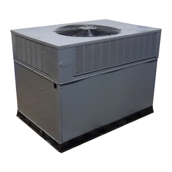
Page 2: Introduction
4 in. (102 mm) thick with 2 in. (51 mm) above grade. (See Fig. 7) The slab should extend approximately 2 in. (51 mm) beyond the The 50JZ (50 Hz) heat pump is fully self-contained and designed casing on all 4 sides of the unit. Do not secure the unit to the slab for outdoor installation (See Fig. - Page 3 Required Clearance for Operation and Service C00160 CENTER OF GRAVITY UNIT HEIGHT UNIT WEIGHT IN. (MM) UNIT ELECTRICAL CHARACTERISTICS IN. (MM) ”A” 50JZ024 400-3-50 135.6 35.02 (889.5) 19.0 (482.6) 18.3 (463.6) 16.0 (406.4) 50JZ030 400-3-50 145.2 37.02 (940.3) 20.0 (508.0) 19.3 (489.0) 17.6 (447.0) 50JZ036...
- Page 4 C00161 CENTER OF GRAVITY UNIT HEIGHT UNIT WEIGHT IN. (MM) UNIT ELECTRICAL CHARACTERISTICS IN. (MM) ”A” 50JZ048 400-3-50 161.0 40.98 (1040.9) 20.0 (508.0) 21.3 (539.8) 18.0 (457.2) Fig. 3—50JZ 048 Unit Dimensions...
-
Page 5: Rig And Place Unit
C00071 CORNER WEIGHTS (SMALL CABINET) CORNER WEIGHTS (LARGE CABINET) Unit Unit Total Weight Total Weight Corner Weight 1 28.5 28.5 Corner Weight 1 34.5 Corner Weight 2 33.5 34.5 Corner Weight 2 Corner Weight 3 Corner Weight 3 43.5 Corner Weight 4 53.5 Corner Weight 4 Fig. - Page 6 ODS CATALOG NUMBER IN. (MM) IN. (MM) IN. (MM) IN. (MM) CPRFCURB006A00 8 (203) 11(279) 161/2 (419) 28-3/4 (730) 50JZ 024-036 CPRFCURB007A00 14 (356) 11(279) 161/2 (419) 28-3/4 (730) CPRFCURB008A00 8 (203) 16 3/16 (411) 17 3/8 (441) 40-1/4 (1022)
- Page 7 MAXIMUM ALLOWABLE DIFFERENCE (in.) C99065 Fig. 6—Unit Leveling Tolerances OPTIONAL OPTIONAL RETURN SUPPLY OPENING OPENING 2" EVAP. COIL COND. COIL C99096 Fig. 7—Slab Mounting Detail HANDHOLD HOOK FEED C99067 Fig. 8—Threading Belt...
-
Page 8: Converting Horizontal Discharge Units To Downflow (Vertical) Discharge Units
914-137" (36"-54") “A” “B” DETAIL A SCALE 0.250 TIGHTEN STRAPPING SECURELY WITH TENSION BUCKLE INSTALL SAFETY STRAPS TO RIGGING CLEVIS AT 4 RIGGING BRACKETS PLACE RIGGING BRACKET ASSEMBLY IN 4 RIGGING HOLES AND INSTALL TIE DOWN STRAP AROUND PERIMETER OF UNIT AND THROUGH SPACE IN BRACKET ASSEMBLY SEE DETAIL A C99075... - Page 9 137 m. cu../min. for high-capacity type. Air filter pressure drop for non-standard filters must not exceed 2.03 mm. wg. The 50JZ units dispose of condensate through a 3/4 in. NPT (19.05 the outlet of the trap is at least 1 in. lower than the drain condensate mm) female fitting that exits on the compressor end of the unit.
- Page 10 Fig. 10—Typical Installation Duct Covers C00092 Fig. 11—50JZ with Duct Covers On condensate connection to ensure proper drainage. Condensate trap (50.8 mm) trap (See Fig. 12). Do not undersize the tube. Pitch the is available as an accessory or is field-supplied. Make sure that the drain trough downward at a slope of at least 1 in.
-
Page 11: Install Electrical Connections
1” (25mm) MIN. TRAP OUTLET 2” (50mm) MIN. C99013 Fig. 12—Condensate Trap Step 7—Install Electrical Connections entry side panel. (See Fig. 2 and 3 for location and size) When the leads are inside the unit, run leads up the high-voltage raceway to the line wiring splice box. - Page 12 Table 4—Electrical Data—50JZ (50Hz) VOLTAGE COMPRESSOR OFM IFM ELECTRIC HEAT POWER SUPPLY DISCONNECT SIZE UNIT 50JZ RANGE V-PH-HZ SIZE Min Max FLA FLA Nominal Kw FLA MCA FUSE OR CKT. BKR MOCP – – 400–3–50 360 32.0 14.4 – 20.6 –...
- Page 13 C02004 Fig. 14—Wiring Schematics...
-
Page 14: Start-Up
THERMOSTAT UNIT CONTROL POWER AND SUBBASE SPLICE BOX C99056 Fig. 15—Control Connections GROUND LUG (IN SLPICE BOX) GROUND LEAD NOTE: Use copper wire only. LEGEND IEC – International Electrical Code Field Wiring Splice Connections C02005 Fig. 16—Line Power Connections START-UP CHECKING COOLING AND HEATING CONTROL OPERA- TION Using the Start-Up Checklist supplied at the end of this book,... -
Page 15: Checking And Adjusting Refrigerant Charge
24 V Circuit Breaker 24 Volt Compartment C99070 Fig. 17—Control Wiring Plate TRANSFORMER CONTAINS A MANUAL RESET OVERCURRENT PROTECTOR IT WILL NOT AUTOMATICALLY RESET DISCONNECT POWER AND INSTALL LOCKOUT TAG PRIOR TO SERVICING THIS COMPARTMENT MUST BE CLOSED EXCEPT WHEN SERVICING C99058 Fig. -
Page 16: No Charge
INDOOR COIL OUTDOOR COIL Bypass Position Metering Position LEGEND HPS – High Pressure Switch LCS – Loss of Charge Switch Accurater Metering Device ® Arrow indicates direction of flow C00095 Fig. 20—Typical Heat Pump Operation, Heating Mode INDOOR COIL OUTDOOR COIL Metering Position Bypass... - Page 17 Table 5—Wet Coil Air Delivery-English Unit 50JZ 024-048* EXTERNAL STATIC PRESSURE (IN. WG) UNIT MOTOR SPEED Watts — — — — — — — — — — — — — — Watts — — — — — — — High —...
- Page 18 Table 7—Fitler Pressure Drop (in. wg)-English FILTER SIZE (IN.) 900 1000 1100 1200 1300 1400 1500 1600 1700 1800 1900 2000 2100 2200 2300 20 X 20 X 1 0.05 0.07 0.08 0.10 0.12 0.13 0.14 0.15 — — — —...
-
Page 19: Indoor Airflow And Airflow Adjustments
Table 12—Superheat Charging Table (Metric) OUTDOOR EVAPORATOR ENTERING AIR TEMPERATURE (°C WB) TEMP (°C) 11.1 11.9 12.8 14.4 16.1 17.8 19.4 20.6 22.2 23.3 25.0 10.0 10.8 11.7 13.3 15.0 16.7 18.3 20.0 21.1 22.2 23.9 – 10.6 11.7 13.3 15.0 16.7 18.3... - Page 20 NOTE: Superheat °F is at low-side service port. Balance Point Worksheet - English 60.00 Based on Indoor Entering Air of 70 F. and Rated CFM 50.00 40.00 30.00 20.00 10.00 0.00 Outdoor Air Temp. (Deg F) C02006 Fig. 22—50JZ Balance Point Worksheet...
-
Page 21: Defrost Control
CESO130076–00 Speedup Quiet Defrost interval Pins Shift DIP switches A99442 Fig. 23—Defrost Control releasing, to observe a complete defrost cycle. When the Quiet with the lead for the desired blower motor speed. The motor speed lead is attached to terminal BM. Insulate removed lead end to Shift switch is selected, compressor will be turned off for two 30 avoid contact with chassis parts. -
Page 22: Maintenance
line or remainder of defrost cycle time up to a maximum defrost Step 2—Indoor Blower and Motor time of 10 minutes. NOTE: All motors are prelubricated. Do not attempt to lubricate 5. Turn off power tag disconnect to outdoor and reconnect fan these motors. -
Page 23: Refrigerant Circuit
C99097 Fig. 24—Refrigerant Circuit screw connections. If any smoky or burned connections are switches are specifically designed to operate with Puron (R-410A) noticed, disassemble the connection, clean all the parts, restrip the systems. R-22 pressure switches must not be used as replacements wire end and reassemble the connection properly and securely. -
Page 24: System Information
Charge refrigerant into suction-line. The information below covers the refrigerant system of the 50JZ, Refrigeration Service Ports including the compressor oil needed, servicing systems on roofs Each unit system has 3 Schrader-type service ports: one on the... -
Page 25: Loss Of Charge Switch
A00010 STATUS No Call for compressor operation FLASHING Reversed phase Normal Fig. 25—Phase Monitor Control and LED Indicators When the thermostat is satisfied, its contacts open, de-engergizing The defrost thermostat signals heat pump that conditions are right contactor and blower relay. Compressor and motors stop. for defrost or that conditions have changed to terminate defrost. - Page 26 FEEDER TUBE STUB TUBE DEFROST THERMOSTAT C99029 Fig. 26—Defrost Thermostat HEAT PUMP WITH PURON—QUICK REFERENCE GUIDE Puron refrigerant operates at 50-70 percent higher pressures than R-22. Be sure that servicing equipment and replacement components are designed to operate with Puron. Puron refrigerant cylinders are rose colored. •...
- Page 27 Table 15—Troubleshooting Chart SYMPTOM CAUSE REMEDY Power Failure Call power company Fuse blown or circuit breaker tripped Replace fuse or reset circuit breaker Defective thermostat, contactor, transformer, control relay, defrost board, or high pressure or loss- Replace component of-charge/low pressure switch Insufficient line voltage Determine cause and correct Compressor and outdoor fan...
- Page 28 † Measured at discharge outlet from compressor. ‡ Measured at liquid line leaving condenser Copyright 2002 CARRIER Corp. • 7310 W. Morris St. • Indianapolis, IN 46231 50jzc1si Manufacturer reserves the right to discontinue, or change at any time, specifications or designs without notice and without incurring obligations.
Need help?
Do you have a question about the 50JZ and is the answer not in the manual?
Questions and answers