Advertisement
Utilitech & UT Design
trademarks of LF, LLC. All rights reserved.
ATTACH YOUR RECEIPT HERE
Serial Number
Questions, problems, missing parts? Before returning to your retailer, call our
customer service department 1-866-994-4148, 8 a.m. - 8 p.m., EST, Monday - Friday.
AB15905
®
are registered
®
Purchase Date
1
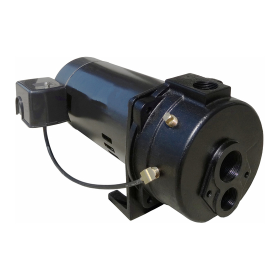
ITEM #0752650
1HP CONVERTIBLE
JET PUMP
MODEL #EFCWJ10-L
Français p. 16
Español p. 31
Lowes.com
Advertisement
Table of Contents

Related Manuals for Utilitech EFCWJ10-L


Summary of Contents for Utilitech EFCWJ10-L
- Page 1 ITEM #0752650 1HP CONVERTIBLE ® JET PUMP MODEL #EFCWJ10-L Utilitech & UT Design are registered ® Français p. 16 trademarks of LF, LLC. All rights reserved. Español p. 31 ATTACH YOUR RECEIPT HERE Purchase Date Serial Number Questions, problems, missing parts? Before returning to your retailer, call our customer service department 1-866-994-4148, 8 a.m.
-
Page 2: Package Contents
PACKAGE CONTENTS PART DESCRIPTION QUANTITY Pump Ejector Short Venturi Tube Long Venturi Tube Nozzle Gasket Bolt Flat Washer SAFETY INFORMATION Please read and understand this entire manual before attempting to assemble, operate or install the product. DANGER • Keep pump equipment out of the reach of children! Failure to follow the directions given could cause serious risk to individuals or objects. - Page 3 SAFETY INFORMATION WARNING • Follow all local electrical and safety codes, as well as the National Electrical Code (NEC) and the Occupational Safety and Health Act (OSHA). • Replace damaged or worn wiring cord immediately. • Do not kink power cable and never allow the cable to come in contact with oil, grease, hot surfaces, or chemicals.
-
Page 4: General Pump Information
PREPARATION Parts Required for Shallow Well Assembly (not included): PVC cement, thread tape, 1-1/4 in. foot valve, (2) 1-1/4 in. male PVC adapters, rigid 1-1/4 in. PVC pipe and couplings, well seal with vent plug, 1-1/4 in. PVC elbow, 1 in. discharge tee, pressure gauge, 1 in. male PVC adapter, 1 in. -
Page 5: Shallow Well Installation
SHALLOW WELL INSTALLATION 1. Thread 1-1/4 in. male PVC adapter (not included) 1-1/4 in. Male into foot valve (not included). Hand tighten, then PVC Adapter tighten 1/4 turn with pipe wrench. Foot Valve 2. Using a 2-step PVC system (not included), attach enough PVC pipe and couplings to the adapter to 1-1/4 in. - Page 6 SHALLOW WELL INSTALLATION 4. Remove pipe clamp and slide well seal (not included) over rigid PVC pipe and onto well casing. Position assembly so that 12 in. of rigid PVC pipe protrude from well seal. Using wrench, turn bolts on well seal Approx.
- Page 7 SHALLOW WELL INSTALLATION 9. Using 2-step PVC system, attach 1-1/4 in. PVC pipe and couplings (not included) as needed to connect the 1-1/4 in. PVC Pipe 1-1/4 in. male PVC adapter to the 1-1/4 in. PVC elbow attached to the top of the well pipe in step 5. NOTE: The horizontal pipe should be level or trending up toward the pump.
- Page 8 SHALLOW WELL INSTALLATION 13. Thread 10 in. x 1 in. nipple into pressure tank (both not included). Thread tank cross into nipple so that the two 1/4 in. holes in tank cross face upward. Plug 1/4 in. Plugs two outlets on tank cross with two 1/4 in. plugs. Tank Cross Nipple 14.
- Page 9 DEEP WELL INSTALLATION Thread 2. The ejector (B) has two holes in the top of it. 1 in. x 5 in. Nipple deep well venturi tube (D) (longer tube) into larger hole 1 in. x 5 in. nipple (not included) into until snug.
- Page 10 DEEP WELL INSTALLATION 5. Remove pipe clamp and slide well seal over PVC pipes and onto well casing. DO NOT let assembly slide down into well. Position assembly so that 12 in. 12 in. of PVC Pipe of PVC pipes protrude from well seal. Using wrench, Protruding From turn bolts on well seal clockwise until rubber gaskets Well Seal...
- Page 11 DEEP WELL INSTALLATION 9. Open pressure regulator kit. Apply 2-3 wraps of thread tape to the male threads on the body of the pressure regulator. With pipe wrench, thread the pressure regulator into 1 in. discharge at top of pump (A). Use a pressure gauge with 1/8 in. NPT thread and thread pressure gauge into side of pump case.
- Page 12 DEEP WELL INSTALLATION 13. Thread boiler drain into front of tank tee. Thread 3/4 in. male PVC adapter into inlet side of tank tee. Connect to household plumbing. 3/4 in. Male Adapter 1/2 in. Boiler Drain PUMP ELECTRICAL CONNECTIONS WARNING •...
-
Page 13: Pump Priming
PUMP ELECTRICAL CONNECTIONS Wiring Pressure Switch To Motor Remove pressure switch cover and follow wiring directions on Ground inside of cover. Be sure to ground wire the pressure switch to Connections the motor. From Line PUMP PRIMING 1. Remove plug or pressure gauge at the top of the Plug pump case. -
Page 14: Troubleshooting
TROUBLESHOOTING PROBLEM POSSIBLE CAUSE CORRECTIVE ACTION Little or no discharge 1. Pump is not primed. 1. Follow priming instructions. 2. Suction lift too high or too long. 2. Move pump closer to water source. Lift should be less than 25 ft. for shallow well installations and less than 90 ft. -
Page 15: Replacement Parts
No warranty or representative not contained herein shall be binding. REPLACEMENT PARTS DESCRIPTION PART NO Ejector Kit 091CJET01 Volute 091CJET02 O-ring 1 091CJET03 O-ring 2 091CJET04 Pressure Switch 091CJET05 Printed in China Utilitech & UT Design® are registered trademarks of LF, LLC. All rights reserved. Lowes.com...
Need help?
Do you have a question about the EFCWJ10-L and is the answer not in the manual?
Questions and answers
need a seal for pump
A well seal is compatible with the Utilitech EFCWJ10-L pump, as mentioned in the installation instructions. It is not included with the pump and must be obtained separately.
This answer is automatically generated