Table of Contents
Advertisement
Available languages
Available languages
Utilitech & UT Design
is a registered
®
trademark of LF, LLC. All rights reserved.
ATTACH YOur rECEiPT HErE
Date Code
Questions, problems, missing parts? Before returning to your retailer, call our customer
service department at 1-866-994-4148, 8 a.m. - 8 p.m., EST, Monday - Friday.
UT950
AB12457
®
IMPORTANT SAFETY INSTRUCTIONS
READ AND FOLLOW ALL INSTRUCTIONS
SAVE THESE INSTRUCTIONS
Purchase Date
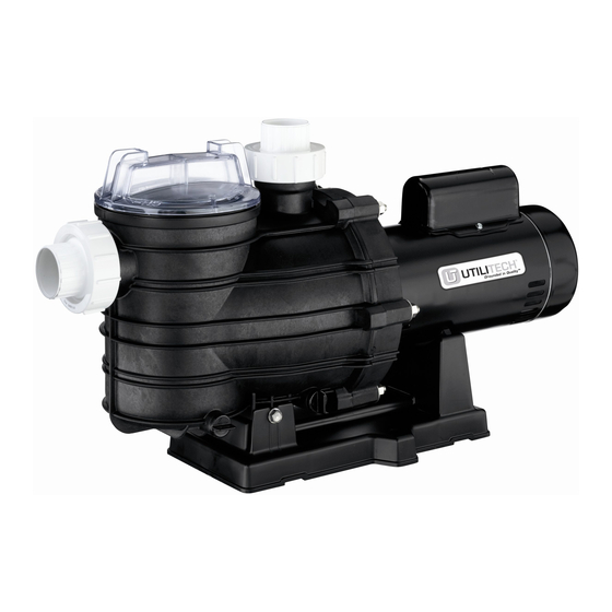
in-grOunD POOl PumP
MODEL #UT2100IGPP, UT2150IGPP
1
ITEM #0240057, 0407163
TWO-SPEED
Español p. 29
1916 1211
Lowes.com
®
Advertisement
Chapters
Table of Contents

Subscribe to Our Youtube Channel
Related Manuals for Utilitech UT2100IGPP


Summary of Contents for Utilitech UT2100IGPP
- Page 1 ITEM #0240057, 0407163 TWO-SPEED ® in-grOunD POOl PumP Utilitech & UT Design is a registered MODEL #UT2100IGPP, UT2150IGPP ® trademark of LF, LLC. All rights reserved. Español p. 29 IMPORTANT SAFETY INSTRUCTIONS READ AND FOLLOW ALL INSTRUCTIONS SAVE THESE INSTRUCTIONS...
-
Page 2: Table Of Contents
TABLE OF CONTENTS Package Contents ....................... 3 Hardware Contents.......................4 Safety Information ....................... 5 Preparation ......................... 8 Installation Instructions ......................9 Operating Instructions .......................17 Care and Maintenance .......................18 Troubleshooting ......................... 24 Warranty ..........................26 Replacement Parts List ....................27 ® Lowes.com... -
Page 3: Package Contents
PACKAgE COnTEnTS PArT DESCriPTiOn QuAnTiTY 6743 1212 Motor canopy Motor Bonding lug Slinger Seal plate Seal plate O-ring Shaft seal Impeller Diffuser Diffuser O-ring Discharge port Trap cover Trap cover O-ring Trap basket Drain plugs Suction port Base *Unit comes preassembled. ®... -
Page 4: Hardware Contents
HARDWARE CONTENTS (SHOWN ACTuAl SizE) Quick connect half union Qty. 2 6684 0912 ® Lowes.com... -
Page 5: Safety Information
SAFETY inFOrmATiOn Please read and understand this entire manual before attempting to assemble, operate or install the product. SAVE THESE INSTRUCTIONS - This manual contains important instructions that should be followed during installation, operation, and maintenance of the product. This is the safety alert symbol. - Page 6 SAFETY inFOrmATiOn risk of suction entrapment. The use of unapproved covers or allowing use of the pool or spa when covers are missing, cracked or broken can result in body or limb entrapment, hair entanglement, body entrapment, evisceration and/or death. The suction at a pool or spa drain or outlet can cause: limb Entrapment: When a limb is sucked or inserted into an opening resulting in a mechanical bind or swelling.
- Page 7 SAFETY INFORMATION SAFETY inFOrmATiOn risk of electric shock. Can shock, burn or kill. Connect only to a branch circuit protected by a Ground Fault Circuit Interrupter (GFCI). The GFCI should be provided by the installer and should be tested on a routine basis. Contact a qualified electrician if you cannot verify that the circuit is protected by a GFCI.
-
Page 8: Preparation
SAFETY inFOrmATiOn • Pressurized air can cause the pump housing, filter, filter lid, or valves to violently separate which can result in severe personal injury or death to anyone near. • To reduce the risk of separation, follow the manufacturer’s instructions to make sure that the filter tank lid and the suction trap cover are properly secured. -
Page 9: Installation Instructions
inSTAllATiOn inSTruCTiOnS general Warnings • All work must be performed by a qualified pool professional and must conform to all current national, state, and local codes. • Install to provide drainage of compartment for electrical components. • These instructions contain information for a variety of pump models and therefore some instructions may not apply to a specific model. - Page 10 inSTAllATiOn inSTruCTiOnS • Code requirements for the electrical connection differ from state to state. Install equipment in accordance with the current National Electrical Code (NEC) and all applicable local codes and ordinances. • Before servicing the pump, switch OFF the pump by disconnecting the main circuit to the pump.
- Page 11 inSTAllATiOn inSTruCTiOnS mounting the Pump Mount the pump on a solid, level, rigid, and vibration-free surface. Mount on concrete platform for quietest performance. Bolt base (Q) to level foundation or mounting bracket. To reduce vibration and pipe stress, bolt pump to concrete foundation. See Figure 2.
- Page 12 inSTAllATiOn inSTruCTiOnS To avoid strains on the pump, support both suction and discharge pipes independently of the pump. Place these supports near the pump. To avoid a strain left by a gap at the last connection, start all piping at the pump and run pipe away from the pump.
- Page 13 inSTAllATiOn inSTruCTiOnS Entrapment Protection The pump suction system must provide protection against the hazard of suction entrapment or hair entrapment/entanglement. See Figure 3. Suction Outlet Covers All suction outlet covers (not included) must be maintained. They must be replaced if cracked, broken, or missing.
- Page 14 inSTAllATiOn inSTruCTiOnS If 100% of the pump’s flow comes from the main drain system, the maximum water velocity in the pump suction hydraulic system must be 6 ft. per second or less even if one main drain (suction outlet) is completely blocked. The flow through the remaining main drain(s) must comply with the latest ASME/ANSI specifications for Suction Fittings For Use in Swimming Pools, Spas, Hot Tubs, and...
- Page 15 inSTAllATiOn inSTruCTiOnS Voltage Voltage at motor must be no more than 10% above or below motor nameplate rated voltage or motor may overheat, causing overload tripping and reduced component life. If voltage is less than 90% or more than 110% of rated voltage when motor is running at full load, consult power company.
- Page 16 inSTAllATiOn inSTruCTiOnS Wiring Pump must be permanently connected to circuit. See recommended fusing data in table below, including correct wire and circuit breaker sizes for the pump alone. If other lights or appliances are also on the same circuit, be sure to add their amp loads to pump amp load before figuring wire and circuit breaker sizes.
-
Page 17: Operating Instructions
OPERATING INSTRUCTIONS NOTICE: Never run pump dry. Running pump dry may damage seals, causing leakage and flooding. Fill pump with water before starting motor. See Figure 7. risk of explosion. May cause risk of fire, separation, severe bodily injury and/or property damage. -
Page 18: Care And Maintenance
OPERATING INSTRUCTIONS NOTICE: If you replace the trap cover O-ring (M) with a non-internally lubricated O-ring, you may need to apply a silicone-based lubricant (not included). Clean and inspect the trap cover O-ring (M); reinstall on trap cover (L). Replace trap cover; turn clockwise to tighten. - Page 19 CArE AnD mAinTEnAnCE Draining the Pump risk of electric shock. Can shock, burn or kill. Disconnect power before working on pump or motor. 1. Pump down water level below all inlets to the pool. risk of electric shock. Can shock, burn or kill.
- Page 20 CArE AnD mAinTEnAnCE maintenance Pump should only be serviced by qualified personnel. For best results, use only genuine factory parts. Be sure to prime the pump before starting. See Figure 8. risk of explosion. May cause risk of fire, separation, severe bodily injury and/or property damage.
- Page 21 CArE AnD mAinTEnAnCE risk of electric shock. Can shock, burn, or kill. Capacitor voltage may be hazardous. 7/16 in. To discharge motor capacitor, hold insulated handle screwdriver BY THE HANDLE and short capacitor terminals together. Do not touch metal screwdriver blade or capacitor terminals. If in doubt, consult a qualified electrician.
- Page 22 CArE AnD mAinTEnAnCE 4. Replace slinger (D) on end of motor shaft so that impeller sleeve will push it into position. If slinger shows signs of wear or damage, Polished surface replace it. Rubber surface 5. Remount seal plate on motor. Torque bolts to 60-80 in./lbs.
- Page 23 OPERATING INSTRUCTIONS 6741 1212 ® Lowes.com...
-
Page 24: Troubleshooting
TrOuBlESHOOTing risk of electric shock. Can shock, burn or kill. • Disconnect power before working on pump or motor. • Read and understand safety/operating instructions in this manual before working on pump! • Only qualified personnel should electrically test pump motor! PrOBlEm POSSiBlE CAuSE COrrECTiVE ACTiOn... - Page 25 TrOuBlESHOOTing PrOBlEm POSSiBlE CAuSE COrrECTiVE ACTiOn If suction and discharge piping are not Pump or piping not adequately supported, pump assembly will be adequately supported strained. See Installation Instructions Do not mount pump on a wooden platform. Mechanical Pump not mounted solidly Securely mount on concrete platform for troubles and noise quietest performance...
-
Page 26: Warranty
WArrAnTY limited Warranty This Limited Warranty is effective June 1, 2011, and replaces all undated warranties and warranties dated before June 1, 2011. The Manufacturer warrants to the original consumer purchaser (“Purchaser” or “You”) that its products are free from defects in material and workmanship for a period of twelve (12) months from the date of the original consumer purchase. -
Page 27: Replacement Parts List
PArTS liST 6742 1212 PArT # (BY mODEl) PArT DESCriPTiOn QTY. uT2100igPP uT2150igPP 1 HP 1-1/2 HP Motor, 230 V, 1 Phase, 2-Speed 62001-1117 PKG 62001-1116 PKG Screw #10-32x1/2 in. U30-692SS Bonding Lug U17-568 Slinger 17351-0009 Seal Plate C3-184P... - Page 28 Printed in U.S.A. Utilitech & UT Design is a ® registered trademark of LF, LLC. All rights reserved. ® Lowes.com...
- Page 29 ARTÍCULO #0240057, 0407163 2 VElOCiDADES ® BOmBA PArA PiSCinAS En El SuElO Utilitech & UT Design® es una marca registrada de LF, LLC. Todos los derechos reservados. MODELO #UT2100IGPP, UT2150IGPP INSTRUCCIONES IMPORTANTES DE SEGURIDAD. LEA Y SIGA TODAS LAS INSTRUCCIONES.
- Page 30 ÍnDiCE Contenido del paquete ...................... 29 Aditamentos........................30 Información de seguridad ....................31 Preparación ........................34 Instrucciones de instalación ....................35 Instrucciones de funcionamiento ..................42 Cuidado y mantenimiento ....................43 Solución de problemas ...................... 48 Garantía..........................50 Lista de piezas de repuesto ....................51 ®...
-
Page 31: Contenido Del Paquete
COnTEniDO DEl PAQuETE 6743 1212 PiEzA DESCriPCiÓn CAnTiDAD Cubierta del motor Motor Orejeta de adherencia Anillo Placa del sello Junta tórica de la placa del sello Sello del eje Impulsor Difusor Junta tórica del difusor Puerto de descarga Cubierta del sifón Junta tórica de la cubierta del sifón Cesta del sifón Tapones de drenaje... -
Page 32: Aditamentos
ADiTAmEnTOS (SE muESTrAn En TAmAñO rEAl) Media unión de conexión rápida Cant. 2 6684 0912 ® Lowes.com... -
Page 33: Información De Seguridad
inFOrmACiÓn DE SEguriDAD Lea y comprenda completamente este manual antes de intentar ensamblar, usar o instalar el producto. GUARDE ESTAS INSTRUCCIONES: Este manual contiene instrucciones importantes que se deben seguir durante la instalación, la operación y el mantenimiento del producto. Este es el símbolo de advertencia de seguridad. - Page 34 inFOrmACiÓn DE SEguriDAD Riesgo de quedar atrapado por la succión. El uso de cubiertas no aprobadas o permitir el uso de la piscina o spa cuando faltan las cubiertas, están agrietadas o rotas puede provocar que el cuerpo, las extremidades o el cabello queden atrapados, desentrañamiento y/o la muerte.
- Page 35 inFOrmACiÓn DE SEguriDAD riesgo de descarga eléctrica. Puede producir una descarga eléctrica, quemaduras o causar la muerte. Conecte solo a un circuito de derivación protegido por un interruptor de circuito de falla de puesta a tierra (GFCI, por sus siglas en inglés). El instalador debe proporcionar el GFCI y se debe probar a modo de rutina.
-
Page 36: Preparación
inFOrmACiÓn DE SEguriDAD • El aire presurizado puede causar que se separen violentamente la carcasa de la bomba, el filtro, la tapa del filtro o las válvulas, lo que puede provocar lesiones personales graves o la muerte de cualquier persona cercana. •... -
Page 37: Instrucciones De Instalación
inSTruCCiOnES DE inSTAlACiÓn Advertencias generales • Todo el trabajo lo debe realizar un profesional de piscinas calificado y debe realizarse de acuerdo con todos los códigos nacionales, estatales y locales actuales. • Instale para proporcionar un drenaje de compartimiento para componentes eléctricos. •... - Page 38 inSTruCCiOnES DE inSTAlACiÓn • Las requisitos de códigos para las conexiones eléctricas cambian según el estado. Instale el equipo de acuerdo con el Código eléctrico nacional (NEC, por sus siglas en inglés) actual y todos los códigos y las ordenanzas locales vigentes.
- Page 39 inSTruCCiOnES DE inSTAlACiÓn montaje de la bomba Monte la bomba en una superficie sólida, nivelada, rígida y sin vibraciones. Monte en una plataforma de concreto para un rendimiento más silencioso. Emperne la base (Q) en un cimiento nivelado o abrazadera de montaje.
- Page 40 inSTruCCiOnES DE inSTAlACiÓn Para evitar tensión en la bomba, apoye el tubo de succión y el de descarga en forma independiente de la bomba. Coloque estos soportes cerca de la bomba. Para evitar la tensión que deja un espacio en la última conexión, comience todas las tuberías en la bomba y lleve el recorrido del tubo alejándose de la bomba.
- Page 41 inSTruCCiOnES DE inSTAlACiÓn Protección para no quedar atrapado El sistema de succión de la bomba debe proporcionar protección contra el peligro de quedar atrapado por la succión o que el cabello se atrape/enrede por ella. Consulte la Figura 3. Cubiertas de salida de succión Todas las cubiertas de salida de succión (no se incluyen) deben recibir mantenimiento.
- Page 42 inSTruCCiOnES DE inSTAlACiÓn Si el 100% del flujo de la bomba viene del sistema de drenaje principal, la velocidad de agua máxima del sistema hidráulico de succión de la bomba debe ser de 1,83 m por segundo o menos, incluso si un drenaje principal (salida de succión) está...
- Page 43 inSTruCCiOnES DE inSTAlACiÓn Voltaje El voltaje del motor no debe tener más de 10% sobre o bajo el voltaje clasificado de la placa de datos del motor o, de lo contrario, el motor podría sobrecalentarse, provocando un apagado por sobrecarga y una menor vida útil del componente.
- Page 44 inSTruCCiOnES DE inSTAlACiÓn temporizador hasta el polo común del interruptor SPDT. AVISO: Conecte el temporizador de modo que solo interfiera en el circuito de baja velocidad. Cableado La bomba debe estar conectada permanentemente al circuito. Consulte los datos de fusibles recomendados en la tabla a continuación, incluidos los tamaños correctos de cable e interruptor de circuito para la bomba sola.
-
Page 45: Instrucciones De Funcionamiento
inSTruCCiOnES DE FunCiOnAmiEnTO AVISO: Nunca haga funcionar la bomba en seco. Hacer funcionar la bomba en seco podría dañar los sellos, provocando fugas e inundaciones. Llene la bomba con agua antes de arrancar el motor. Consulte la Figura 7. Riesgo de explosión. Podría causar un riesgo de incendio, separación, lesiones corporales graves y/o daños a la propiedad. -
Page 46: Cuidado Y Mantenimiento
inSTruCCiOnES DE FunCiOnAmiEnTO AVISO: Si reemplaza la junta tórica de la cubierta del sifón (M) por una que no esté internamente lubricada, es posible que necesite aplicar un lubricante a base de silicona (no se incluye). Limpie e inspeccione la junta tórica de la cubierta del sifón (M);... - Page 47 CuiDADO Y mAnTEnimiEnTO Drenaje de la bomba riesgo de descarga eléctrica. Puede producir una descarga eléctrica, quemaduras o causar la muerte. Desconecte la alimentación antes de trabajar en la bomba o el motor. Bombee hasta que el nivel del agua quede por debajo de todas las entradas a la piscina..
- Page 48 CuiDADO Y mAnTEnimiEnTO mantenimiento Solo personal calificado debe darle servicio a la bomba. Para obtener los mejores resultados, use solo piezas de fábrica originales. Asegúrese de cebar la bomba antes de arrancarla. Consulte la Figura 8. Riesgo de explosión. Podría causar un riesgo de incendio, separación, lesiones corporales graves y/o daños a la propiedad.
- Page 49 CuiDADO Y mAnTEnimiEnTO riesgo de descarga eléctrica. Puede producir una descarga eléctrica, quemaduras o causar la muerte. El voltaje del capacitor puede ser peligroso. Para descargar el capacitor del motor, sostenga un destornillador con manija aislante DE LA MANIJA 7/16 in. y corte los bornes del capacitor juntos.
- Page 50 CuiDADO Y mAnTEnimiEnTO Vuelva a colocar el anillo (D) en el extremo del eje del motor de modo que el manguito del impulsor lo presione en su posición. Si el anillo muestra Polished Superficie indicios de desgaste o daño, reemplácelo. surface Superficies pulida...
- Page 51 CuiDADO Y mAnTEnimiEnTO 6741 1212 ® Lowes.com...
-
Page 52: Solución De Problemas
SOluCiÓn DE PrOBlEmAS riesgo de descarga eléctrica. Puede producir una descarga eléctrica, quemaduras o causar la muerte. • Desconecte la alimentación antes de trabajar en la bomba o el motor. • Lea y comprenda las instrucciones de seguridad/operación de este manual antes de trabajar con la bomba. - Page 53 SOluCiÓn DE PrOBlEmAS PrOBlEmA CAuSA POSiBlE ACCiÓn COrrECTiVA Verifique el voltaje de línea; si es menos de 90% o de más de 110% del voltaje clasificado, consulte con un electricista certificado Problema eléctrico La bomba puede Apriete todas las conexiones eléctricas estar demasiado caliente Aumente la ventilación...
-
Page 54: Garantía
gArAnTÍA garantía limitada Esta garantía limitada es válida desde el 1 de junio de 2011 y remplaza todas las garantías sin fechar y las garantías con fecha anterior al 1 de junio de 2011. El Fabricante garantiza al comprador original (“Comprador” o “Usted”) que sus productos no presentarán defectos de material ni de mano de obra durante un período de doce (12) meses desde la fecha de compra original del consumidor. -
Page 55: Lista De Piezas De Repuesto
DE PiEzAS DE rEPuESTO 1169 0794 FP PiEzA # (POr mODElO) PiEzA DESCriPCiÓn CAnT. uT2100igPP uT2150igPP 1 HP 1-1/2 HP Motor, 230 V, 1 fase, de 2 velocidades 62001-1117 PKG 62001-1116 PKG Tornillo #10-32x1/2 pulg U30-692SS Orejeta de adherencia... - Page 56 Impreso en EE.UU. Utilitech & UT Design® es una marca registrada de LF, LLC. Todos los derechos reservados ® Lowes.com...
Need help?
Do you have a question about the UT2100IGPP and is the answer not in the manual?
Questions and answers