Advertisement
Quick Links
Advertisement

Related Manuals for Siemens Servo Ventilator 300


Summary of Contents for Siemens Servo Ventilator 300
- Page 1 Servo Ventilator 300/300A Service Manual E382 E380E 061 01 03 01...
- Page 2 Ventilator 300/300A are given in Pa (bar). used. Airway pressures are given in cm H • Some parts in the Servo Ventilator 300/ 1 hPa = 1 mbar 1 mbar = 1 hPa 300A are comprised by a spare parts 1 kPa = 10 mbar 1 mbar = 0.1 kPa...
- Page 3 Servo Ventilator 300/300A Important Important To the responsible service personnel • The Servo Ventilator 300/300A must be serviced at regular intervals by specially • The contents of this document are not trained personnel. The service intervals, binding. If any significant difference is...
- Page 4 Notes Servo Ventilator 300/300A Notes Siemens-Elema AB E382 E380E 061 01 03 01...
-
Page 5: Table Of Contents
Servo Ventilator 300/300A Contents Contents 1. Introduction ................2. Description of functions............21 3. Disassembling and assembling ......... 81 4. Service procedures............... 103 5. Troubleshooting ..............109 6. Product change history ............113 7. Index ..................115 8. Diagrams ................. 121... - Page 6 Servo Ventilator 300/300A Notes Notes Siemens-Elema AB E382 E380E 061 01 03 01...
- Page 7 Servo Ventilator 300/300A Introduction 1. Introduction Main units ..........8 Basic principles ........12 E382 E380E 061 01 03 01 Siemens-Elema AB...
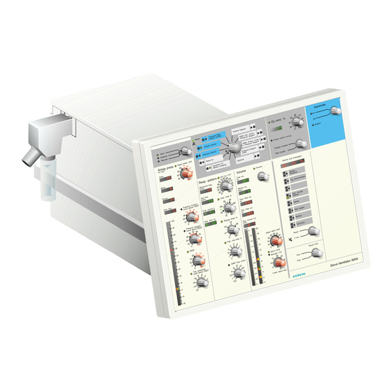
- Page 8 Introduction Servo Ventilator 300/300A Main units The Servo Ventilator 300 can be divided into two main units: • Control unit (1). The control unit consists of the panel section (2) and the control section (3). • Patient unit (4). The patient unit consists of the pneumatic section (5) and the power section (6).
- Page 9 Servo Ventilator 300/300A Introduction Control unit The control unit consists of the control section which is a housing with a number of PC boards. The panel section, attached to the control section, is the other part of the control unit.
- Page 10 Introduction Servo Ventilator 300/300A All PC boards in the control section (except PC 1617 mentioned above) are accessible when the control section cover is removed. These PC boards are: • PC 1605 & (1) with PC REFERENCE TIMING 1588 MICROPROCESSOR MODULE PROM •...
- Page 11 Servo Ventilator 300/300A Introduction When the pneumatic section casing and the cover plate is removed, the following parts are accessible: • PC 1615 EXPIRATORY FLOW LINEARIZATION with PC 1588 MICROPROCESSOR MODULE PROM • Housing (2) containing PC 1585 CURRENT and PC 1586...
- Page 12 Introduction Servo Ventilator 300/300A Basic principles Siemens-Elema AB E382 E380E 061 01 03 01...
- Page 13 Servo Ventilator 300/300A Introduction Gas flow through the patient unit Inspiratory flow Expiratory flow 1. Gas inlet for air. The connected air must 8. The patient system's expiratory gas tube have a pressure between 200 and 650 is connected at the expiratory inlet. The kPa (2 and 6.5 bar).
- Page 14 Introduction Servo Ventilator 300/300A Feedback control system – General CONTROLLING CONTROLLED SYSTEM TRANSDUCER ELEMENT SIGNAL AMPLIFIER (WITH SERVO) COMPARING ELEMENT CONTROLLING SYSTEM ACTUAL VALUE CONVERTER ERROR ACTUATING SIGNAL SIGNAL "COMPENSATOR" "ERROR REFERENCE DESIRED CALCULATOR" VARIABLE VALUE PID-CONTROLLER 300-A08E may comprise one P-action gives a continuous basic positioning.
- Page 15 Servo Ventilator 300/300A Introduction Inspiratory feedback control system REFERENCE INSPIRATORY CONTROLLED SYSTEM TRANSDUCERS & TIMING VALVE PRESSURE FLOW POSITION VALVE SENSOR SOLENOID SUPPLY FLOW PRESS. ACTUAL ACTUAL INSP. VALVE POSITION FLOW SUPPLY GAS FLOW REF. PRESS. VALUE ACTUAL POSITION VALUE...
- Page 16 Introduction Servo Ventilator 300/300A In addition to the main forward path, compensating elements are added as described in both inspiratory feedback control system pictures. The compensating elements in this system works as follows: • Using the input information of ACTUAL...
- Page 17 Servo Ventilator 300/300A Introduction Inspiratory feedback control system (cont'd) REFERENCE & TIMING PRESSURE REF. INSPIRATORY TRANSDUCERS DESIRED PRESS. CONTROLLED SYSTEM VALVE VALUE POSITION VALVE INSP. PRESSURE FLOW PRESSURE SENSOR SOLENOID ACTUAL PRESS. VALUE PRESS. SUPPLY FLOW PRESS. CONTR. ACTUAL ACTUAL FLOW INSP.
- Page 18 Introduction Servo Ventilator 300/300A Notes Siemens-Elema AB E382 E380E 061 01 03 01...
- Page 19 Servo Ventilator 300/300A Introduction Expiratory feedback control system TRANSDUCER EXPIRATORY CONTROLLED SYSTEM VALVE POSITION VALVE PRESSURE SENSOR SOLENOID EXP. PRESSURE EXP. VALVE POSITION ACTUAL POSITION VALUE ACTUAL ACTUAL CURRENT VALUE EXPIRATORY PRESSURE VALUE CURRENT CONTROL POSITION PD PEEP PID POSITION EXP.
- Page 20 Introduction Servo Ventilator 300/300A Principle diagram EXTERNAL EXTERNAL CONTROL UNIT PATIENT UNIT CONTROL OUTPUT SIGNALS SIGNALS FROM PATIENT INPUT FROM SV 300 INTERNAL CONTROL MICROPROCESSORS COMPUTER INTERFACE SIGNALS INPUT SIGNALS EXP. INPUT SIGNALS FLOW MONITORING PRESSURE AMPLIFIER EXP. PRESSURE PRESSURE...
- Page 21 Servo Ventilator 300/300A Introduction Inspiratory regulation Monitoring 1. Choice between pressure regulation and 10. The board monitors and MONITORING flow regulation during inspiration is generates certain displayed parameters. made by the dependent on the It also activates alarm functions. MODE CPU Mode selection.
- Page 22 Introduction Servo Ventilator 300/300A Notes Siemens-Elema AB E382 E380E 061 01 03 01...
-
Page 23: Description Of Functions
Servo Ventilator 300/300A Description of functions 2. Description of functions General ............ 22 Microprocessor module PC 1588 .... 23 Version labels .......... 24 Control unit – Panel section ..... 25 Front panel ........25 1A Automode front panel ...... 27 Panel interface ........ - Page 24 General As described in chapter Introduction, the In this Description of functions, the words Servo Ventilator 300 can be divided into two inspiratory and expiratory are used in the Main units; Control unit and Patient unit. The first place to indicate the site of a part (e g two main units are connected to each other INSPIRATORY CHANNEL).
- Page 25 Servo Ventilator 300/300A Description of functions Microprocessor module PC 1588 includes a green/red WATCHDOG D1 (3). The LED indications are as follows: PC 1588 – Green LED: Microprocessor program is , PC1588 (1), is MICROPROCESSOR MODULE running. included on each one of the following five PC boards: –...
- Page 26 Description of functions Servo Ventilator 300/300A Version labels A label (1) showing all PROM-versions included in the ventilator is attached to the control section. When replacing a PROM, attach the new label (2) that is delivered with the new PROM onto the old label on the control section.
- Page 27 Servo Ventilator 300/300A Description of functions Control unit – Panel section 1.1 Patient range selection For selection of one of three available The Panel section consists of the main patient ranges: blocks 1 – 2 which are described below. • 1 three-position selector. This switch...
- Page 28 Description of functions Servo Ventilator 300/300A 1.2 Airway pressure 1.3 Respiratory pattern For control and monitoring of For control and/or monitoring of respiratory AIRWAY parameters: pattern parameters: PRESSURE • 4 four-character LED displays. • 4 four-character LED displays • 1 double column LED bargraph.
- Page 29 Servo Ventilator 300/300A Description of functions 1.5 O concentration 1.8 Mode selection For control and monitoring of O For the selection of Ventilation Modes and concentration parameters: control of the Set Parameter Guide functions: • 1 four-character LED display. Showing information generated via 2.1...
- Page 30 Description of functions Servo Ventilator 300/300A 2 Panel interface 2.3 Inputs Analog multiplexor for input signals to the This main block consists of the board block 2.1 PC 1614 including its PANEL CPU PANEL INTERFACE PC1588 . The board MICROPROCESSOR MODULE is connected (via N18, N19 and N40) to the 2.4 LED matrix...
- Page 31 Servo Ventilator 300/300A Description of functions 2.8 Opto switch 2A Automode panel interface Time multiplexed driving stage and sensor receiving stage for all the infra-red sensor The board PC 1745 AUTOMODE PANEL INTERFACE touch pads on the front panel. The function contains electronics for handling of the is controlled by the block 2.1...
- Page 32 As the board PC 1587D was included in these mandatory upgrades, all SV 300/300A Only accessories, supplies or auxiliary must be equipped with PC 1587D (or higher). equipment listed in Siemens-Elema catalogs (”Products and accessories” Order No. The main block consists COMPUTER INTERFACE 90 34 562 E323E and ”Spare and exchange...
- Page 33 An information message is also displayed on as described in the COMMUNICATION PORTS Servo Screen 390 if such unit is connected Reference Manual "Servo Ventilator 300/ to the SV 300. 300A, Computer Interface (Firmware version Note – The voltage level measured in the 2.X)", Order No.
- Page 34 PC 1587. The LEDs are visible munication protocol, see Reference Manual if the control section cover is removed. "Servo Ventilator 300/300A, Computer Interface (Firmware version 2.X)", Order No. 63 14 061 E380E. The connectors are identical with one exception;...
- Page 35 Servo Ventilator 300/300A Description of functions 3A Computer interface D2 – D5: . Error indications TEST STATUS LED during System startup test. The startup test dummy is divided in several sequences. The PC 1665 COMPUTER INTERFACE DUMMY The first sequence is a LED test that starts...
- Page 36 Description of functions Servo Ventilator 300/300A 4 Monitoring 4.1 Monitor/Alarm CPU including MON-PROM functions This main block consists of the board This block includes the board PC 1588 with PC 1608 including its PC 1588 MONITORING . Some details of the PC 1588...
- Page 37 Servo Ventilator 300/300A Description of functions 4.1.1 Airway pressure PMA: P ; signal from main block 12 INSP PRESSURE INSPIRATORY PRESSURE ; signal from main block 13 PRESSURE EXPIRATORY PRESSURE LIM_PRESS.L = Signal from the block 6.1 including functions. MODE CPU...
- Page 38 Description of functions Servo Ventilator 300/300A 4.1.2 O concentration PMA: concentration = Signal generated within the block 4.1 using . signal from CONC the block 11.3 which is digitally compensated for mean airway pressure and CELL barometric pressure according to signal from 4.6...
- Page 39 Servo Ventilator 300/300A Description of functions 4.1.4 Exp. minute volume PMA: Exp. min. vol. = signal from the block 4.4 & FLOW FILTERS INTEGRATORS Reference value M = Preset Upper alarm limit for Expired minute volume Reference value M = {The highest of the following two possibilities:} = Preset Lower alarm limit for Expired minute volume or = Lowest value for normal (digital) alarm;...
- Page 40 Description of functions Servo Ventilator 300/300A 4.1.6 Gas supply PMA: Measured gas supply pressures = Air supply pressure = Oxygen supply pressure Alarm table: ” ” : r i > : r i > : r i < & &...
- Page 41 Servo Ventilator 300/300A Description of functions 4.1.7 Battery PMA: Measured voltage levels. External power voltage level: The block 21.3 VOLTAGE & indicates, by the signal, in case the external CONTROL TIMING INTERNAL BATTERY MODE main and external battery power voltages are both too low.
- Page 42 Description of functions Servo Ventilator 300/300A 4.1.8 Technical PMA 1: Start up test results. Signals generated within the main block 4. . The start MONITORING uptest is made once each time the Mode selector is turned from the position Off.
- Page 43 Servo Ventilator 300/300A Description of functions PMA 2: Microprocessor failure. Signals from each of the following blocks: (PC 1614 PANEL CPU PANEL INTERFACE (PC 1587 MICROPROCESSOR CPU COMPUTER INTERFACE (PC 1605 & MODE CPU REFERENCE TIMING (PC 1616 MIXER CPU INSPIRATORY CONTROL 18.1...
- Page 44 Description of functions Servo Ventilator 300/300A PMA 3: Monitored front panel inputs. Signals from each of the following blocks: (from Patient range selector) PATIENT RANGE SELECTION (from CMV freq. setting - double potentiometer) RESPIRATORY PATTERN (from O concentration setting - double potentiometer) CONCENTRATION (from Mode selector via 2.8 Mode select - Input stage)
- Page 45 Servo Ventilator 300/300A Description of functions PMA 5: Internal supply voltages. Failure signal from Power Failure Monitor hardware (part of the block 4.5 BACKUP ALARM SYSTEM Reference values (alarm limits) according to 4.5 BACKUP ALARM SYSTEM Alarm table: ” ”...
- Page 46 Description of functions Servo Ventilator 300/300A PMA 7: OverrangeErr signal from 7.1 ,indicating high Ref. value for flow, and the MIXER CPU following Tidal Volume signals: = Tidal Volume output value from Insp. Flow Integrator (block 4.4 ) = Tidal Volume output value from Exp. Flow Integrator (block 4.4 ) = Tidal Volume value according to Front panel setting (corresp.
- Page 47 Servo Ventilator 300/300A Description of functions 4.2 Inputs interface & A/D 4.5 Backup alarm system Multiplexor and analog to digital conversion The internal power supply voltages are stages for input signals to the main block monitored in this block. If any of the voltage...
- Page 48 Description of functions Servo Ventilator 300/300A 4.5.1 Supply voltage PMA = Internal supply voltages. Reference values as shown in the following Alarm table. Alarm table: ± % ± ± – l i t > < The signal will activate functions to open the...
- Page 49 Servo Ventilator 300/300A Description of functions 4.5.3 O concentration PMA = O concentration; signal generated within the block 4.5 using . signal from CONC the block 11.3 which is analogically compensated for barometric pressure according CELL signal from 4.6 BAROMETER PRESSURE...
- Page 50 – Operating Manual. failure or in case of a internal failure. For a further functional description of the 4.7 Loudspeaker , contact your Siemens representative. For audible alarm generated by the regular (digital) monitor/alarm block 4.1 MONITOR ALARM CPU 4.8 Beeper Tone generator for audible alarm controlled by the (analog) block 4.5...
- Page 51 Servo Ventilator 300/300A Description of functions 6 Reference & Timing Flow regulation For flow regulation the signal FLOW REGULATION This main block consists of the board is directly used by the block 7.3 FLOW REF MIXER PC 1605 & including its...
- Page 52 Description of functions Servo Ventilator 300/300A Pressure regulation Pressure Reg. Volume Control (PRVC) mode and Volume Support (VS) mode For pressure regulation the signal PRESSURE is used by the block 6.4 The value of REGULATION PRESSURE REF PRESSURE REGULATION PRESSURE REF...
- Page 53 Servo Ventilator 300/300A Description of functions A calculation is made at the end of inspiration The parameter f is calculated every breath CALC n to achieve a new calculated pressure value (in VS mode). In breath number n the value is...
- Page 54 Description of functions Servo Ventilator 300/300A F is one of two possible functions (6) or (7) The change of pressure reference level stated below although the value of F used from one breath to the next breath during when performing the calculation according...
- Page 55 Servo Ventilator 300/300A Description of functions The change of pressure reference level from Pressure Support/CPAP mode one breath to the next breath within these 4 Pressure Support mode: breaths is 75% of the change of pressure as This mode is active if the front panel setting...
- Page 56 Description of functions Servo Ventilator 300/300A 6.1.2. Respiratory timing time and that period is used for this offset zeroing. Timing is defined by the internal respiratory phase control signals for Additionally, timing control of the offset INSP TIME PAUSE which are generated in this...
- Page 57 Servo Ventilator 300/300A Description of functions Timing conditions for Start and for Stop of INSPIRATION valid during different modes of ventilation: i l l > : ] ) i l l > S " " s S " " s...
- Page 58 Description of functions Servo Ventilator 300/300A Explanation of Start and Stop conditions; Stop conditions Front panel setting on which it depends: (0) Ventilator stop insp.; Time duration since last start insp. = = (Preset insp. time %) x 1/100 x Breath...
- Page 59 Servo Ventilator 300/300A Description of functions (9) Measured Insp. tidal volume > When above mentioned condition is true it 125% x Preset Insp. tidal volume; will lead to the following timing: Preset Insp. tidal vol. (A) Use of the mode Pressure Reg. Volume (10) Measured Insp.
- Page 60 Description of functions Servo Ventilator 300/300A Additional timing conditions applicable (0) When using Pause time [in Volume for SV 300A control or SIMV (Volume control) mandatory breath]: As long as the front panel setting for Start of Pause time. Automode is in position Off and also Else: Start of Expiration time.
- Page 61 Servo Ventilator 300/300A Description of functions The automatic switch back from above Conditions at which the trigger signal PATIENT mentioned Support mode to its correspon- is activated: TRIG ding Control mode will take place at the • When the front panel setting Trigger...
- Page 62 Description of functions Servo Ventilator 300/300A 6.3 End inspiration indicator drop up to 15 cm H O is compensated in this way. During inspiration time when pressure regulation is used, except in Pressure The actuating signal from the PRESSURE PID Control mode or mandatory breaths in output is used by the block 7.3...
- Page 63 Servo Ventilator 300/300A Description of functions 7 Inspiratory control 7.2 Inputs This block is a multiplexor for input signals This main block consists of the board to the main block 7 PC 1616 including its INSPIRATORY CONTROL INSPIRATORY CONTROL PC 1588.
- Page 64 Description of functions Servo Ventilator 300/300A 8.1 Air inlet Patient unit – Pneumatic section The air inlet nipple is a quick-coupling where compressed air is connected to the The Pneumatic section consists of the main ventilator. The design of the air inlet nipple blocks 8 –...
- Page 65 Servo Ventilator 300/300A Description of functions 8.3 Inspiratory valve temperature 8.7 Inspiratory solenoid with sensor position sensor The temperature of the supplied gas is The gas flow through the INSPIRATORY VALVE measured by the is regulated by the INSPIRATORY VALVE...
- Page 66 Description of functions Servo Ventilator 300/300A 8.10 Pressure amplifier 8.13 Delta pressure amplifier amplifies the input The input signal from 8.5 PRESSURE AMPLIFIER DELTA PRESSURE signal from 8.4 is amplified in the SUPPLY PRESSURE TRANSDUCER TRANSDUCER DELTA PRESSURE The output signal from this amplifier, .
- Page 67 Servo Ventilator 300/300A Description of functions 8.19 Flow PI control 8.15 Flow calculator Controller block comparing actual The flow depending signal from 8.13 AIR FLOW DELTA from the block 8.15 with and the absolute supply FLOW CALCULATOR PRESSURE AMPLIFIER desired signal compensated in pressure depending signal from 8.11...
- Page 68 Description of functions Servo Ventilator 300/300A 8.22 Current power Consists of the board PC 1586 CURRENT POWER Driving stage for the energy going to the block 8.7 INSPIRATORY SOLENOID WITH POSITION . The result of the output signal is a...
- Page 69 Servo Ventilator 300/300A Description of functions 9 Inspiratory valve unit – O 10 Inspiratory valve unit – Optional – works in the INSPIRATORY VALVE UNIT same way as the 8 – If the third valve slot is not used for equip-...
- Page 70 Description of functions Servo Ventilator 300/300A 11 Inspiratory channel 11.3 O cell The O cell is mounted in a holder on the The fresh gas from the INSPIRATORY VALVES 11.2 and protected by a and 9) is mixed and lead to the patient INSPIRATORY PIPE bacteria filter.
- Page 71 Servo Ventilator 300/300A Description of functions 11.4 Safety valve 11.5 Safety valve driver The safety valve function depends on its consists of the SAFETY VALVE DRIVER solenoid and on its factory trimmed springs. electronic board PC 1613 with three The solenoid can be electrically activated connection cables: only from the 11.5...
- Page 72 Description of functions Servo Ventilator 300/300A 12 Inspiratory pressure 12.3 Pressure amplifier This board PC 1611 contains: The function of this main block is to measure the pressure in the 11 INSPIRATORY • a pressure transducer and generate a corresponding signal CHANNEL •...
- Page 73 Servo Ventilator 300/300A Description of functions 13 Expiratory pressure 14 Expiratory channel The function of this main block is to The expiratory channel conveys the measure the pressure in the 14 expiratory gas from the patient system EXPIRATORY and generate a signal through the patient unit.
- Page 74 Description of functions Servo Ventilator 300/300A is situated on the 14.4 The change in resistance in the 14.3 EXPIRATORY FLOW EXPIRA . The more flow in the channel, the is converted to a AMPLIFIER TORY FLOW TRANSDUCER higher the pressure on the strain gauge. The corresponding signal voltage.
- Page 75 Servo Ventilator 300/300A Description of functions 15 Valve control 15.3 O concentration amplifier This block, the This main block consists of the board CONCENTRATION AMPLIFIER amplifies the signal from 11.3 PC 1622 CELL VALVE CONTROL The output signal is amplified to 90 mV/%O at 1013 mbar (760 mmHg) ambient 15.1 PEEP PID control...
- Page 76 Description of functions Servo Ventilator 300/300A 16 Expiratory valve 16.3 Expiratory solenoid with position sensor The function of this main block is to controls the opening squeeze the 14.5 in a EXPIRATORY SOLENOID EXPIRATORY VALVE TUBE through the 14 regulated way.
- Page 77 Servo Ventilator 300/300A Description of functions 18Expiratory flow 18.4 Expiratory flow linearizer linearization Analog linearizing circuit using the unlinear flow signal from the 14.4 EXPIRATORY FLOW This main block consists of the board generating a linear signal AMPLIFIER PC 1615 .
- Page 78 Description of functions Servo Ventilator 300/300A 19 Cooling system Patient unit – Power section 19.1 Cooling fan The Power section consists of the main blocks 20 – 22 which are described below. is an axial fan for 24 V COOLING FAN power supply.
- Page 79 Only accessories, supplies or auxiliary The power supply +24 V at N77 and N78 equipment listed in Siemens-Elema catalogs is disconnected if: (”Products and accessories” Order No. • The ventilator runs in internal battery 90 34 562 E323E and ”Spare and exchange mode parts”...
- Page 80 Description of functions Servo Ventilator 300/300A 21.2 Voltage distribution 21.3 Voltage control & Timing The different voltage levels used in the This block administrates the different power ventilator are regulated in and distributed supply sources. from this block. The fuse F1, rated F 6.3 A, If power suppy is lower than the limits limits the total +24 V supply current.
- Page 81 Servo Ventilator 300/300A Description of functions 21.4 Power temperature control 22 Operating power A NTC-resistor on PC 1618 senses the air 22.1 Internal battery temperature inside the power section. There are two 12 V sealed lead acid If the air temperature inside the power batteries connected in series inside the section exceeds approx.
- Page 82 Description of functions Servo Ventilator 300/300A 22.3 Operating time meter 23 Interconnection cable The operating time meter on the power is the 2.95 m long INTERCONNECTION CABLE section panel is supplied with +5 V. This 89 leads cable that connects the Control unit means that the operating time meter will be with the Patient unit.
-
Page 83: Disassembling And Assembling
Servo Ventilator 300/300A Disassembling and assembling 3. Disassembling and assembling General ............ 82 Preparations ..........82 Handling PC boards ......... 83 Microprocessor module PC 1588 .... 84 Exchanging PROMs ........ 85 Separating the panel section from the control section ......86 Disassembling the panel section ..... - Page 84 Disassembling and assembling Servo Ventilator 300/300A General The different main units and sub-units of the Servo Ventilator 300 are described in chapter Introduction. This information can be useful also when disassembling and assembling the Servo Ventilator 300. Disassembling and assembling of the...
- Page 85 Servo Ventilator 300/300A Disassembling and assembling Handling PC boards The PC boards contain components that are highly sensitive to static electricity. Those who come into contact with circuit boards containing sensitive components must take certain precautions to avoid damaging the components (ESD protection).
- Page 86 Disassembling and assembling Servo Ventilator 300/300A Microprocessor module Removing PC 1588 PC 1588 • Remove the securing device (see above). Remove any remaining glue strips on the Each one of the five PC boards PC 1605, connector sides PC 1608, PC 1614, PC 1615 and PC 1616 includes a microprocessor module.
- Page 87 Servo Ventilator 300/300A Disassembling and assembling Exchanging PROMs On each of the PC-boards PC 1587 and PC 1588, there are exchangable program memory modules, PROMs. The PROMs are denominated and labelled as follows: – COM-PROM (PC 1587). Divided into two PROM chips –...
- Page 88 Disassembling and assembling Servo Ventilator 300/300A Separating the panel section from the control section • Remove the four screws (1). • Carefully lift off the panel section (2). The panel section is now separated from the control section (3). Disassembling the panel...
- Page 89 Servo Ventilator 300/300A Disassembling and assembling Panel interface board PC 1614 • Separate the panel section from the control section as previously described. • Disconnect all front panel control connectors (1) from PC 1614. • Remove all nuts (2) holding PC 1614.
- Page 90 Disassembling and assembling Servo Ventilator 300/300A Assembling the panel section The procedure for assembling the panel section is the reverse of the disassembly procedure previously performed. The following points must be noted during assembling: Panel interface board PC 1614 • Carefully mount PC 1614 on the front panel base plate.
- Page 91 Servo Ventilator 300/300A Disassembling and assembling • Tighten the nut (6). Tighten to approx.: – 150 Ncm on the mode selector knob – 90 Ncm on all other knobs. Use the knob holder tool, Order No. 62 04 197 E380E, when mounting the control knob.
- Page 92 Disassembling and assembling Servo Ventilator 300/300A Disassembling the control section PC boards PC 1587, PC 1605, PC 1608 and PC 1616 • Remove the screws (1) and lift off the control section lid (2). • To remove any of the boards PC 1605 (3), PC 1608 (4) or PC 1616 (5), grasp the PC board and pull it out.
- Page 93 Servo Ventilator 300/300A Disassembling and assembling Control interconnection board PC 1617 • Separate the panel section from the control section as previously described. • Remove PC boards PC 1587, PC 1605, PC 1608 and PC 1616 as previously described. • Disconnect the two interconnection cable connectors (1) from the control unit.
- Page 94 Disassembling and assembling Servo Ventilator 300/300A Assembling the control section The procedure for assembling the control section is the reverse of the disassembly procedure previously performed. The following points must be noted during assembling: PC boards • The PC boards are mounted in different types of guides.
- Page 95 Servo Ventilator 300/300A Disassembling and assembling Separating the pneumatic section from the power section • Place the patient unit on the edge of the workbench so the screws are accessible from below. • Loosen the four screws (1). • Lift off the pneumatic section from the power section.
- Page 96 Disassembling and assembling Servo Ventilator 300/300A Disassembling the power section Mains power inlet • Separate the pneumatic section from the power section as previously described. • Remove the cover (1). On older units: A small plastic cover mounted with two screws (2).
- Page 97 Servo Ventilator 300/300A Disassembling and assembling Power supply board PC 1618 • Separate the pneumatic section from the power section as previously described. • Remove the cover (1) from the mains power inlet. • Remove the four screws (2). • Disconnect the;...
- Page 98 Disassembling and assembling Servo Ventilator 300/300A Assembling the power section The procedure for assembling the power section is the reverse of the disassembly procedure previously described. The following points must be noted during assembling: Mains power inlet • Connect the cables to the mains power inlet according to figure.
- Page 99 Servo Ventilator 300/300A Disassembling and assembling Battery pole covers • Make sure that the battery pole covers are mounted on the battery poles according to figure. Assembling the pneumatic section to the power section The procedure for assembling the pneumatic section to the power section is the reverse of the separating procedure previously performed.
- Page 100 Disassembling and assembling Servo Ventilator 300/300A Disassembling the pneumatic section Inspiratory valves (gas modules) • Remove the screw (1). • Push down the safety catch (2). • Pull out the inspiratory valve (3). • If the inspiratory valve unit – Optional (4)
- Page 101 Servo Ventilator 300/300A Disassembling and assembling Cover plate • Remove the inspiratory valves for AIR and as previously described. • Remove the pneumatic section casing as previously described. • Disconnect the flow transducer cable (1). • Disconnect the O cell cable (2).
- Page 102 Disassembling and assembling Servo Ventilator 300/300A Pneumatic interconnection board PC 1607 • Separate the pneumatic section from the power section as previously described. • Remove the cover plate as previously described. • If an inspiratory valve – Optional (1) is mounted, loosen the screw (2) and remove the valve dummy.
- Page 103 Servo Ventilator 300/300A Disassembling and assembling Assembling the pneumatic section The procedure for assembling the pneumatic section is the reverse of the disassembly procedure previously performed. The following points must be noted during assembling: Cover plate • The silicon rubber connection pieces for...
- Page 104 Disassembling and assembling Servo Ventilator 300/300A Removing the inter- connection cable Patient unit connection • Remove the pneumatic section casing as previously described. • Disconnect the two interconnection cable connectors (1). • Remove the two screws (2). • Slide out the cable clamp (3) from the patient unit.
-
Page 105: Service Procedures
Servo Ventilator 300/300A Service procedures 4. Service procedures Selecting the language and barometric pressure unit ....... 104 Selecting the address code ....105 Selecting the voltage setting ....105 Replacing the fuses ....... 106 Replacing the internal battery ....107... - Page 106 Service procedures Servo Ventilator 300/300A Selecting the language and barometric pressure unit The following selections are made with the switch SW1 on PC 1608 MONITORING – The language of the text shown in the ”Alarms and messages” display. – The unit of the actual barometric pressure shown in the ”Alarms and messages”...
- Page 107 Servo Ventilator 300/300A Service procedures Selecting the address code The ventilators address code is selected with two switches SW1 and SW2 on PC 1587 COMPUTER INTERFACE The switches are located above SERIAL 1 and they are accessible COMMUNICATION PORT when the upper cover is opened.
- Page 108 Service procedures Servo Ventilator 300/300A Replacing the fuses Fuses F1, F2, F3 and F4 Fuses F1 – F4 are mounted on PC 1618 inside the power section. POWER SUPPLY • Disconnect and prepare the ventilator as described in chapter ”3. Disassembling and assembling”, section ”Preparation”.
- Page 109 Servo Ventilator 300/300A Service procedures Replacing the internal battery Normal service interval for exchange of the internal batteries is approx. 3 years. The lifetime of the internal batteries are reduced if the batteries are used frequently to supply the ventilator with operating power.
- Page 110 Service procedures Servo Ventilator 300/300A Replacing the battery on Resetting the trend data PC 1587 Computer Interface memory and real time clock Normal service interval for exchange of the The trend data memory and the real time battery is approx. 5 years.
-
Page 111: Troubleshooting
Servo Ventilator 300/300A Troubleshooting 5. Troubleshooting Troubleshooting table ......110 E382 E380E 061 01 03 01 Siemens-Elema AB... - Page 112 Troubleshooting Servo Ventilator 300/300A All possible ”Alarm and messages” texts Before starting troubleshooting, try to and alarm conditions can be found in chapter eliminate all possibilities of operational ”2. Description of functions”, section errors. If the malfunction remains, use the ”4.
- Page 113 Servo Ventilator 300/300A Troubleshooting ” ” µ & µ µ l i f . ) t Multiple monitoring and uP errors can be an indication of power supply error. E382 E380E 061 01 03 01 Siemens-Elema AB...
- Page 114 Troubleshooting Servo Ventilator 300/300A Notes Siemens-Elema AB E382 E380E 061 01 03 01...
-
Page 115: Product Change History
Servo Ventilator 300/300A Product change history 6. Product change history PROM, PC board and Operating Manual versions ....114 E382 E380E 061 01 03 01 Siemens-Elema AB... - Page 116 Due to upgrades performed on delivered Version 7.X – Describes the functions of ventilators, the PROM, PC board and Servo Ventilator 300 with Failure Alarm Operating Manual versions as listed below Box (FAB). should be used with the Servo Ventilator Version 8.X –...
-
Page 117: Index
Servo Ventilator 300/300A Index 7. Index Alphabetic index ........116 Functions Included in PC board E382 E380E 061 01 03 01 Siemens-Elema AB... - Page 118 Index Servo Ventilator 300/300A Functions Included in PC board A/D, D/A Computer interface PC 1587 – – – – Address code Computer interface PC 1587 – – – – Air inlet Inspiratory valve unit – Air – – – –...
- Page 119 Servo Ventilator 300/300A Index Functions Included in PC board Delta pressure amplifier Inspiratory valve unit – Air PC 1602 – – – – Delta pressure transducer and net Inspiratory valve unit – Air – – – – – End inspiration indicator Reference &...
- Page 120 Index Servo Ventilator 300/300A Functions Included in PC board Inputs interface & A/D Monitoring PC 1608 – – – – Inspiratory channel – – – – – Inspiratory control – PC 1616 – Inspiratory mixing part Inspiratory channel – –...
- Page 121 Servo Ventilator 300/300A Index Functions Included in PC board Monitor/Alarm CPU including MON-PROM functions Monitoring PC 1608 – – Monitoring – PC 1608 – Monitor display Panel interface PC 1614 – – – – Nozzle unit Inspiratory valve unit – Air –...
- Page 122 Index Servo Ventilator 300/300A Functions Included in PC board Pressure amplifier (Insp. valve) Inspiratory valve unit – Air PC 1601 – – – – Pressure calculator Inspiratory valve unit – Air PC 1601 – – – – Pressure PID control Reference &...
-
Page 123: Diagrams
Servo Ventilator 300/300A Diagrams 8. Diagrams External battery inlet P67 ...... 122 Auxiliary output N77 ......122 Auxiliary output N78 ......123 Master/Slave connection N80 ....123 Analog I/O terminal N81 ......124 Serial communication ports N82 and N83 Analog input & Digital code port N84 .. - Page 124 3-pole Cannon AXR connector (P67). Can be 9-pole D-sub connector (N77). Mainly used used to connect an external battery to the for power supply to auxiliary equipment. Servo Ventilator 300. Only Siemens Only Siemens connection cable must be connection cable must be used. used.
- Page 125 15-pole D-sub connector (N78). Mainly used 15 pole D-sub connector (N80). Can be used for power supply to auxiliary equipment. for the synchronization of two Servo Only Siemens connection cable must be Ventilator 300. Only Siemens connection used. cable must be used.
- Page 126 J2 and J3, indicates for connection of monitoring/recording which connectors that need to be short- equipment. Only Siemens connection cable circuited with a jumper to enable a control must be used. signal. (Signal No. as stated in the pin configuration list below.)
- Page 127 The connectors are identical The illustration of the connector show with one exception; the internal clock can outside view. only be set via N82. Only Siemens connection cable must be used. The illustration of the connector show outside view. N82 / N83 –...
- Page 128 Diagrams Servo Ventilator 300/300A Interconnection cable Connected at Connected at is the 2.95 m long INTERCONNECTION CABLE patient unit control unit 89 leads cable that connects the Control unit with the Patient unit. Signal names and pin Pin No. Signal name Pin No.
- Page 129 Servo Ventilator 300/300A Functional block diagram Letter codes shown within a circle in the Functional block diagram Code Refers to block function PC board No(s) Inspiratory valve unit – Air ..PC 1585, 1586, 1593, 1600, 1601, 1602, 1603, 1637 –...
- Page 131 E382 E380E 061 01 03 02 Order No.: 60 26 905 E380E © Siemens-Elema AB, Electromedical Systems Division, 1992-1997. All rights reserved. No part of this publication Printed in Sweden. may be reproduced, stored in a retrieval system, or transmitted in any form or by any means, electronic, mechanical, TK 198 photocopying, recording, or otherwise, without the prior permission of the copyright owner in writing.
Need help?
Do you have a question about the Servo Ventilator 300 and is the answer not in the manual?
Questions and answers