
Related Manuals for ALFAtron SCK41TS


Summary of Contents for ALFAtron SCK41TS
- Page 1 ALFATRON ELECTRONICS GmbH GERMANY SCK41TS 6x1(with 2 Shared inputs) 4K Presentation Switcher with HDBaseT Version: SCK41TS_2021V1.1...
-
Page 2: Table Of Contents
1. Product Introduction ....................1 1.1. Features ......................1 1.2. Package List ..................... 1 2. Specification ....................... 2 2.1. SCK41TS Switcher ................... 2 2.2. TPBHD70-R Receiver ..................4 3. Panel Description ......................5 3.1. Switcher Front Panel ..................5 3.2. Switcher Rear Panel ..................6 3.3. - Page 3 ALF-SCK41TS 6.6. EDID Tab ......................20 6.6.1. EDID Setting ..................20 6.6.2. EDID Upload ..................21 6.7. Network Tab ....................21 6.8. Tags Tab ......................22 6.9. Security Tab ....................22 6.10. Additional Tab ....................23 6.11. GUI Upgrade ....................23 7.
- Page 4 ALF-SCK41TS FCC Statement This equipment generates, uses and can radiate radio frequency energy and, if not installed and used in accordance with the instructions, may cause harmful interference to radio communications. It has been tested and found to comply with the limits for a Class B digital device, pursuant to part 15 of the FCC Rules.
-
Page 5: Product Introduction
ALF-SCK41TS 1. Product Introduction The ALF-SCK41TS 6x1(with 2 Shared inputs) 4k presentation switcher offers four HDMI, one shared display port and one shared USB-C input along with mirrored HDMI and HDBaseT outputs. The HDBaseT output supports PoC and can be paired with a compatible HDBaseT receiver to extend 4k@30Hz/1080P signal up to 40 meters (131ft) / 70 meters (230ft) all over a single CATx cable respectively. -
Page 6: Specification
ALF-SCK41TS 2. Specification 2.1. SCK41TS Switcher Video Input Video Input (4) HDMI IN (1~4), (1) DP, (1) USB-C Video Input Connector (4) Type-A female HDMI, (1) DisplayPort, (1) Type-C USB HDMI: Up to 4K@30Hz 4:4:4 Input Resolution DP: Up to 4K@30Hz 4:4:4... - Page 7 ALF-SCK41TS L-R Level Deviation < 0.3dB, 1kHz sine at 0dBFS level (or max level before clipping) Output Load Capability 1KΩ and higher (Supports 10x paralleled 10KΩ loads) Noise Level -80dB SPDIF Audio Output SPDIF Out (1) SPDIF Audio Out Connector...
-
Page 8: Tpbhd70-R Receiver
ALF-SCK41TS 2.2. TPBHD70-R Receiver Input Input Signal (1) RJ-45; (1) RS232 (1) 3.5mm mini jack; (1) RJ-45; (1) 3p captive screw Input Connector connector Output Output (1) HDMI; (1) IR; (1) RS232 (1) Type A, female HDMI; (1) 3.5mm mini jack; (1) 3p... -
Page 9: Panel Description
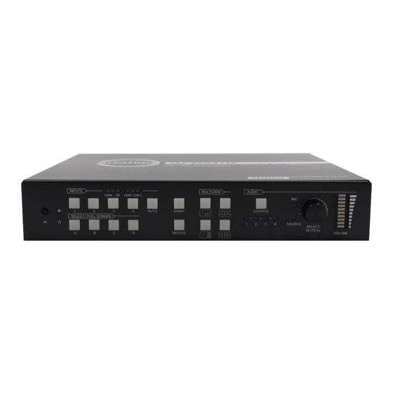
6x1 4K Presentation Switcher with HDBaseT 3. Panel Description 3.1. Switcher Front Panel INPUTS MULTIVIEW AUDIO HDMI HDMI USB-C AUTO SWAP SOURCE SELECT / FULL SCREEN SOURCE SELECT MUTE/3s VOLUME RESIZE ① IR LED: Built-in IR sensor, receives IR signal sent from IR remote. ②... -
Page 10: Switcher Rear Panel
ALF-SCK41TS 3.2. Switcher Rear Panel AUDIO IN AUDIO OUT CONTROL Phantom 48V) LINE SPDIF CONTACT IN IR IN IR OUT IR EYE FIRMWARE RS232 TCP/IP HDBT 1. HDMI 2. HDMI 3. HDMI 3. DP 4. HDMI 4. USB-C HDMI INPUTS... -
Page 11: Receiver Front And Rear Panel
ALF-SCK41TS 3.3. Receiver Front and Rear Panel Name Description HDBT Link status indicator: OFF: No Link LINK ① GREEN:Link Successful Blinking GREEN: Link abnormal HDCP compliant indicator OFF: No HDMI traffic (no picture) ② HDCP GREEN: Traffic with HDCP. -
Page 12: System Connection
ALF-SCK41TS 3.4. System Connection... -
Page 13: Front Panel Control
ALF-SCK41TS 4. Front Panel Control 4.1. Multi-view Mode Selection There are four multi-view modes can be selected by front panel buttons. The factory default multi-view mode is quartered window mode, and there is a one-one correspondence between the four input sources and the four output windows: input 1 ->... -
Page 14: Window Size Setting
ALF-SCK41TS 4.4. Window Size Setting The window A/B/C/D size can be adjusted by repeatedly pressing the RESIZE button, the button LED lights once when pressing its button once. Please refer the GUI Multi- view Tab for further details. Example: PIP (Picture in Picture) -
Page 15: Switching Status Inquiry
ALF-SCK41TS Auto Switching Press AUTO button to enable or disable auto-switching mode. Note: Auto switching mode only works in full screen mode. When in auto mode, the switcher will switch according to the following rules: The switcher will switch to the available active inputs with the priority: 1-HDMI > 2- ... -
Page 16: Ir Remote Control
ALF-SCK41TS 5. IR Remote Control The switch provides an IR EYE port for the IR receiver connection, it can then be controlled by the below IR remote. Note: There is no long-press functionality on this IR remote, the button functions are the same as the front panel buttons. -
Page 17: Gui Control
ALF-SCK41TS 6. GUI Control The switcher can be controlled via TCP/IP. The default IP settings are: IP Address: 192.168.0.178 Subnet Mask: 255.255.255.0 Type 192.168.0.178 in the internet browser, it will enter the below log-in webpage: Username: admin Password: admin Type the user name and password, and then click Login to enter the section for video... -
Page 18: Control Tab
ALF-SCK41TS 6.1. Control Tab 6.1.1. Video Control The source selection buttons, Auto button and window A~D buttons, are same as the buttons of the front panel. Please find 4.5 Video Signal Switching for more details. Click “Power Off” to enter the system into standby mode. -
Page 19: Audio Control
ALF-SCK41TS Command: Type command in this box to be sent to control the display device, and then click “Send”. Relay 1~2: The function is for projection screen control, and the HDBaseT receiver which is connected to the switcher needs to have two relay ports. Click “Manual”, the projection screen will either roll up or drop down, click “Manual”... -
Page 20: Multiview Tab
ALF-SCK41TS 6.2. Multiview Tab 1) Pre-defined Up to 16 multi-view modes can be selected. RESIZE: Click the button to adjust the window size. Note that only Layout 2, Layout 5~Layout 8, Layout 9~Layout 12 can have the window size adjusted. -
Page 21: Display Setting Tab
ALF-SCK41TS 2) User-defined User Layout: Select the user-defined layout number 1~4. Window Select: Select the input source for each window, and then adjust window size by setting start position and end position. Click “Save” to save the user-defined layout. -
Page 22: Resolution Tab
ALF-SCK41TS Automatic Display Control: Enable or disable the function to automatically control the display device. No Signal Timeout: Set the auto power off time that the display device will automatically power off after no signal is detected and the setting time is up. -
Page 23: Cec Tab
ALF-SCK41TS 6.5. CEC Tab 6.5.1. Source Control Select the HDMI input source which needs to be controlled, then click the function buttons. 6.5.2. Display Control Select the output display device which needs to be controlled, then click the ... -
Page 24: User-Defined Cec Command
ALF-SCK41TS 6.5.3. User-defined CEC Command Select input source or display device, then type CEC command in the corresponding Trigger 1 or Trigger 2 box to be sent to control the selected device. 6.6. EDID Tab 6.6.1. EDID Setting Select the compatible built-in EDID for the selected input source. -
Page 25: Edid Upload
ALF-SCK41TS 6.6.2. EDID Upload Upload user-defined EDID via the below steps: Step 1: Prepare the EDID file (.bin) on the control PC. Step 2: Click the user-defined box, and then select the EDID file (.bin). Step 3: Click “Apply” to upload the user-defined EDID. -
Page 26: Tags Tab
ALF-SCK41TS 6.8. Tags Tab Modify the multiview layout labels. 6.9. Security Tab Modify the login password. Lock or unlock the front panel buttons. ... -
Page 27: Additional Tab
ALF-SCK41TS 6.10. Additional Tab Set the baud rate of switcher and restore the switcher to factory default setting. 6.11. GUI Upgrade Please visit http://192.168.0.178:100 for GUI online upgrade. Type the username and password (the same as the GUI log-in setting, modified password will be available only after rebooting) to login to the configuration interface. -
Page 28: Rs232 Control
ALF-SCK41TS 7. RS232 Control The RS232 port of switcher has two control methods. 1) Local control: Connect the RS232 port to a control device (e.g.PC) to control the switcher via RS232 commands. 2) Display device control: The RS232 port is used with the RS232 port of far-end HDBaseT receiver to control the display device (e.g. -
Page 29: System Commands
ALF-SCK41TS 7.1. System Commands Command Example and Command Description Feedback >GetFirewareVersion Get the firmware version. <V1.0.0 >SetFactoryReset Factory Default <FactoryReset_True >SetReboot System reboot. <Reboot_EN >SetHelp SetAV <Select the input source >SetAV InParam,OutParam InParam = 1~6 1 - HDMI 1 Get the command details. -
Page 30: Signal Switching Commands
ALF-SCK41TS 7.2. Signal Switching Commands Command Example and Command Description Feedback Switch input source to output window. [InParam] = 1 ~ 6 >SetAV 3 1 - HDMI 1 >SetAV 1,A 2 - HDMI 2 >SetAV 3 - HDMI 3 [InParam],[OutParam]... -
Page 31: Audio Setting Commands
ALF-SCK41TS 7.3. Audio Setting Commands Command Example and Command Description Feedback >SetMicAudioMute EN Mute/Unmute microphone audio. >SetMicAudioMute [Param] = EN, Dis >SetMicAudioMute Dis [Param] EN - Mute. <MicAudioMute True Dis - Unmute (Default) <MicAudioMute False >GetMicAudioMute Get the microphone audio mute status <MicAudioMute False... -
Page 32: Function Setting Commands
ALF-SCK41TS Command Example and Command Description Feedback >GetAudioDelay Get the delay time of audio output. <AudioDelay 20 7.4. Function Setting Commands Command Example and Command Description Feedback Set the baud rate of RS232 port to [Param]. >SetRS232Baudrate 5 [Param] = 1 ~ 5 1 - 115200 >SetRS232Baudrate... - Page 33 ALF-SCK41TS Command Example and Command Description Feedback [Param1] = 1 ~ 6 1 - HDMI 1 2 - HDMI 2 3 - HDMI 3 4 - DP 3 5 - HDMI 4 >SetInPortEdid 6 - USB-C 4 <InPortEdid 1,1 [Param1],[Param2]...
- Page 34 ALF-SCK41TS Command Example and Command Description Feedback 15 - 4 WINDOWS PIP 1F3U 16 - 4 WINDOWS PIP 1F3D 17 - USER CONFIG 1 18 - USER CONFIG 2 19 - USER CONFIG 3 20 - USER CONFIG 4 >GetMvMode Get multiview mode <MvMode 1...
- Page 35 ALF-SCK41TS Command Example and Command Description Feedback Set the delay time to send CEC, RS232 >SetPanelCEC and standby commands after removing <PanelCEC 9 [Param] input signal removed. [Param] = 0~1800 (s) (Default: 600s) Get the delay time to send CEC, RS232 >GetPanelCEC...
-
Page 36: Cec Commands
ALF-SCK41TS 7.5. CEC Commands Command Example and Command Description Feedback Send CEC MENU command to source >SetCecSrcMenu 1 device. [Param] = 1 ~ 4 >SetCecSrcMenu 1 - HDMI 1 [Param] 2 - HDMI 2 <CecSrcMenu 1 3 - HDMI 3 4 - HDMI 4 >SetCecSrcUp 1... - Page 37 ALF-SCK41TS Command Example and Command Description Feedback <CecSrcFastForward 1 >SetCecDisplayOn 1 >SetCecDisplayOn Send CEC ON command to display device. [Param] [Param] = 1 ~ 2 (1 - HDMI, 2 - HDBT) <CecDisplayOn 1 >SetCecDisplayOff >SetCecDisplayOff 1 Send CEC OFF command to display device.
-
Page 38: Special Commands
ALF-SCK41TS 7.6. Special Commands Note: The below commands do not need ending mark. Command Example and Command Description Feedback Set the ASCII “Display Input Select” command "XXXX" to be sent to display >SetDisplayInputSendCha device when power on the switcher. r_5:1234567... - Page 39 ALF-SCK41TS Command Example and Command Description Feedback 2 - 57600 3 - 38400 <Baudrate: 9600 4 - 19200 <Power on to send 5 - 9600 HEX:30 31 32 33 XX XX= HEX data to be sent (X = 0~9, A~F and up to 20 XX).
-
Page 40: Firmware Upgrade
ALF-SCK41TS 8. Firmware Upgrade 1) Prepare the latest upgrade file (.bin) and rename it as “FW_MV bin” on PC. 2) Power off the switcher and connect the FIRMWARE port of switcher to the PC with a type-A USB cable. 3) Power on the switcher, the PC will automatically detect a U-disk named “BOOTDISK”. -
Page 41: After-Sales Service
ALF-SCK41TS 9.After-sales Service Should you experience problems using the Alfatron SCK41TS, please refer to the manual and troubleshooting and maintenance section (6). Should the error persist, note that any transport costs of the equipment to the distributor are borne by the user during the warranty. - Page 42 ALF-SCK41TS Limited warranty in respect of Alfatron Products Only 1.1 This limited warranty covers defects in materials and workmanship in this product. 1.2 Should warranty service be required, proof of purchase must be presented to the Company. The serial number on the product must be clearly visible and not have been tampered with in any way whatsoever.
- Page 43 ALF-SCK41TS 1.10.1 Elect to repair or facilitate the repair of any defective parts within a reasonable period of time, free of any charge for the necessary parts and labor to complete the repair and restore this product to its proper operating condition.; or 1.10.2 Replace this product with a direct replacement or with a similar product deemed...
Need help?
Do you have a question about the SCK41TS and is the answer not in the manual?
Questions and answers