Table of Contents
Advertisement
Advertisement
Table of Contents

Related Manuals for Slamtec RPLIDAR A1


Summary of Contents for Slamtec RPLIDAR A1
-
Page 1: Contents
Shanghai Slamtec.Co.,Ltd... -
Page 2: Table Of Contents
Contents CONTENTS ..............................1 OVERVIEW ..............................3 ........................3 TEMS IN THE EVELOPMENT RPLIDAR A1 ..............................4 USB A ..............................4 DAPTER CONNECTION AND USAGE ........................5 ..............................5 ONNECTION USB A ......................6 NSTALL RIVER FOR THE DAPTER ..........................7 PPLICATION ............................ -
Page 3: Overview
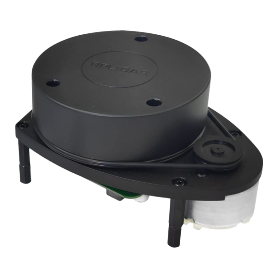
Overview RPLIDAR A1 development kit includes the matched tools used for evaluating RPLIDAR A1’s performance and initial development. After connecting the RPLIDAR A1 with PC via USB cable and adapter, Users can observe the cloud map of the environment scanning point collected by the RPLIDAR A1 and start development based on the SDK. -
Page 4: Rplidar A1
RPLIDAR A1 usage and interface definition will be introduced in the coming sections. USB Adapter Figure 1-3 RPLIDAR A1 Adapter RPLIDAR A1 development kit contains a USB adapter to provide power supply for RPLIDAR A1 and convert RPLIDAR A1 internal UART serial interface to USB interface. 4 / 16 Copyright (c) 2009-2013 RoboPeak Team Copyright (c) 2013-2016 Shanghai Slamtec Co., Ltd. -
Page 5: Connection And Usage
2) Connect the USB adapter to your PC using the Micro-USB cable. After connecting RPLIDAR A1 to your PC through the USB cable, the LED in the bottom of the RPLIDAR A1 will light up and RPLIDAR A1 start scanning. -
Page 6: Install Driver For The Usb Adapter
Silicon Labs’ official website: http://www.silabs.com/products/interface/usb-bridges/Pages/usb-bridges.aspx Here’s the installation steps in Windows: After connecting the RPLIDAR A1 with PC, please find the driver file “CP210x VCP Windows” and choose correct operating system version accordingly: x86 for 32- bit OS and x64 for 64-bit OS. -
Page 7: Run Demo Application
Figure 2-5 Recognized Serial Port Name Matched with the USB Adapter Run Demo Application SLAMTEC provides a Lidars plugin in RoboStudio for users in test and evaluation. You can view the scan result directly in the UI and save the scan result to files for further processing. - Page 8 2. Click Serial Ports to extend the lidar lists and you’ll find the RPLIDAR A1 previously connected to your PC; 3. Click the RPLIDAR A1 icon to extend the tool buttons below the icon: the left one is to adjust the motor speed(RPLIDAR A1 is not adjustable by default.) while...
- Page 9 Figure 2-7 The Lidar Plugin in RoboStudio The serial number, version and model of the RPLIDAR A1 will show next with its icon in the lidar control panel. The supported commands of RPLIDAR are showed in the tool bar. The descriptions are listed in the bellow table.
-
Page 10: Troubleshooting
When the scan core or the laser power works abnormally, the scan core will enter protection mode. This state can be retrieved via SDK API. If such scenario happened, please send restart command to reset the scan core. 10 / 16 Copyright (c) 2009-2013 RoboPeak Team Copyright (c) 2013-2016 Shanghai Slamtec Co., Ltd. -
Page 11: Sdk Introduction And Usage
RPLIDAR A1 Pin Definition and Specification In the development kit, the bottom motor interface and core interface of the RPLIDAR A1 module use PH1.25-3P and PH1.25-4P vertical mounts respectively. Users can use a cable connection with 1.25mm-pitch 3pin and 1.25mm-pitch 4pin terminals. -
Page 12: Pin Definition For The Usb Adapter
MOTOCTL Pin used to control scan motor speed to adjust RPLIDAR A1’s scan frequency, PWM signal also can be applied. The equivalent circuit showed as bellow: Figure 3-2 RPLIDAR A1 MOTOCTL Equivalent Circuit Reference Design for RPLIDAR A1 development RPLIDAR... -
Page 13: Configure Rplidar A1 Scan Frequency
By connecting MOTOCTL signal to the device has PWM output function such as MCU’s PWM output I/O port, RPLIDAR A1’s scan frequency can be locked in a proper value by adjust duty ratio of PWM using the scan frequency feedback provided by RPLIDAR A1 core. -
Page 14: Pre-Heating For Best Performance
Pre-Heating for Best Performance The scan core will be heating when start working. We recommend pre-heating RPLIDAR A1 (Start the scan mode and the scan motor is rotating) for more than 2 minutes to get the best measurement accuracy. Ambient Temperature RPLIDAR A1’s measurement resolution is sensitive to the ambient temperature. -
Page 15: Revision History
Revision History 15 / 16 Copyright (c) 2009-2013 RoboPeak Team Copyright (c) 2013-2016 Shanghai Slamtec Co., Ltd. -
Page 16: Appendix
3-2 RPLIDAR A1 MOTOCTL E IGURE QUIVALENT IRCUIT ..................12 3-3 RPLIDAR A1 P IGURE EFERENCE ESIGN ......................12 3-4 RPLIDAR A1 USB A IGURE DAPTER EFINITION ....................13 16 / 16 Copyright (c) 2009-2013 RoboPeak Team Copyright (c) 2013-2016 Shanghai Slamtec Co., Ltd.
Need help?
Do you have a question about the RPLIDAR A1 and is the answer not in the manual?
Questions and answers