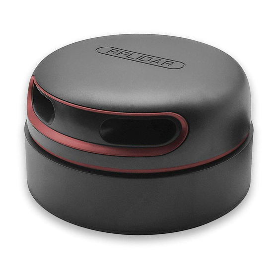
Summary of Contents for Slamtec RPLIDAR
-
Page 1: Contents
RPLIDAR Low Cost 360 Degree Laser Range Scanner Introduction to Standard SDK S h a n g h a i S la m te c .C o .,L td... -
Page 2: Table Of Contents
USAGE ..............................11 UNTIME CONSISTENCY ........................... 11 SDK H EADERS ..............................11 SDK I NITIALIZATION AND ERMINATION ......................12 RPLIDAR ........................12 ONNECTING TO AN OTOR TART AND ONTROL ....................... 13 EASUREMENT CAN AND CQUIRING ....................13 RPLIDAR..................14 ETRIEVING... -
Page 3: Introduction
An ultra-simple command line application demonstrates the simplest way to connect to an RPLIDAR device and continuously fetching the scan data and outputting the data to the console. Users can quickly integrate RPLIDAR to their existing system based on this demo application. -
Page 4: Build Sdk And Demo Applications
If you’re developing under Windows, please open VS solution file sdk_and_demo.sln under workspaces\vc10 or workspaces\vc9. It contains the SDK project and all demo application projects. Figure 1-2 The RPLIDAR Standard SDK Solution File 4 / 17 Copyright (c) 2009-2013 RoboPeak Team... - Page 5 “make DEBUG=1” to do Debug build. The generated binary can be found under the following folders: Linux o output\Linux\Release o output\Linux\Debug. MacOS o output\Darwin\Release o output\Darwin\Debug. Figure 1-3 Develop RPLIDAR Standard SDK in Linux 5 / 17 Copyright (c) 2009-2013 RoboPeak Team Copyright (c) 2013-2017 Shanghai Slamtec Co., Ltd.
-
Page 6: Cross Compile
SDK root folder. The common usage is: CROSS_COMPILE_PREFIX=<COMPILE_PREFIX> ./cross_compile.sh e.g. CROSS_COMPILE_PREFIX=arm-linux-gnueabihf ./cross_compile.sh ultra_simple The demo application simply connects to an RPLIDAR device and outputs the scan data to the console: 6 / 17 Copyright (c) 2009-2013 RoboPeak Team... - Page 7 Figure 2-1 ultra_simple Demo Application Data Output Steps: 1) Connect RPLIDAR to PC by using the provided USB cable. (The chip transforming the USB to serial port is embedded in the RPLIDAR development kit) 2) Start application by using the following command: Windows ultra_simple <com_port>...
-
Page 8: Simple Grabber
User can print all scan data if needed. Figure 2-2 simple_grabber Demo Application Data Output Steps: 1) Connect RPLIDAR to pc using provided USB cable. (USB to serial chip embedded in RPLIDAR development kit) 2) Start application use command: simple_grabber <com number>... -
Page 9: Frame Grabber
This demo application can show real-time laser scan data in the GUI with 0-360 degree environment range data. Note, this demo application only has win32 version. Figure 2-3 frame_grabber Demo Application Data Output 9 / 17 Copyright (c) 2009-2013 RoboPeak Team Copyright (c) 2013-2017 Shanghai Slamtec Co., Ltd. - Page 10 Steps: 1) Connect RPLIDAR to pc using provided USB cable. (USB to serial chip embedded in RPLIDAR development kit) 2) Choose correct com port number through com port selection dialog. 3) Press start scan button (marked in red in the figure above) to start.
-
Page 11: Sdk Usage And Development Guide
Then please change SDK settings accordingly. SDK Headers rplidar.h Usually, you only need to include this file to get all functions of RPLIDAR SDK. rplidar_driver.h This header defines the SDK core drive interface: the RPLidarDriver class. Please refer to demo applications ultra_simple or simple_grabber to understand how to use it. -
Page 12: Sdk Initialization And Termination
RPlidarDriver *RPlidarDriver::CreateDriver (_u32 drivertype) Each RPlidarDriver instance is bound to only one RPLIDAR device at the same time. But user programs can freely allocate arbitrary number of RPlidarDriver instances and make them communicates with multiple RPLIAR devices concurrently. -
Page 13: Motor Start And Stop Control
Request RPLIDAR to stop the motor rotating. Figure 3-1 RPLIDAR Functions Related to Motor Control Note: as described in the previous section, the RPLIDAR SDK will call stopMotor to stop the rotating of motor by default when invoking the interface connect. -
Page 14: Retrieving Other Information Of An Rplidar
Note: the startScan() and stop() functions don’t control the scanning motor of the RPLIDAR directly. The host system should control the scanning motor to rotate or stop via the PWM pin. -
Page 15: The Operations Related To The Accessory Board
The Operations Related to the Accessory Board For the accessory board included in some RPLIDAR development kits, since the board supports speed control via PWM, this feature can be implemented by invoking the following functions: Function Name Brief description Check whether the accessory board supports the PWM control. -
Page 16: Revision History
Added description about the newly added interface of 1.5.2 2016-05-03 Added new interface startMotor/stopMotor Updated connect interface and set stopMotor called by default 2017-05-15 Release 1.0 Version 16 / 17 Copyright (c) 2009-2013 RoboPeak Team Copyright (c) 2013-2017 Shanghai Slamtec Co., Ltd. -
Page 17: Appendix
3-3 RPLIDAR F IGURE UNCTIONS RELATED TO ETRIEVING THER NFORMATION PERATION ......14 3-4 RPLIDAR F IGURE UNCTIONS RELATED TO THE CCESSORY OARD ..............15 17 / 17 Copyright (c) 2009-2013 RoboPeak Team Copyright (c) 2013-2017 Shanghai Slamtec Co., Ltd.


Need help?
Do you have a question about the RPLIDAR and is the answer not in the manual?
Questions and answers