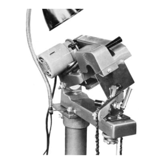
Summary of Contents for Foley 308
- Page 1 OPERATING INSTRUCTIONS 3 0 8 FOLEY SAW CHAIN GRINDER SERVICE MANUAL NO. R001088 / i V , FOLEY MANUFACTURING COMPANY 3300 FIFTH STREET NORTHEAST MINNEAPOLIS, MINNESOTA 55418...
- Page 2 ONE YEAR GUARANTEE All Foley equipment is guaranteed to be sturdily constructed and free of defects in workmanship or material. If within one year from date of shipment, any parts should prove defective, replacement parts will be furnished free of charge when defective part is returned postpaid for inspection.
- Page 5 OF MODEL 308 FOLEY SAW CHAIN GRINDER IMPORTANT It is very simple to operate the Foley Grinder. All you need do is learn the adjustments before starting to grind your first chain. This will save you time and trouble. First read all the gen- eral instructions given in the manual.
-
Page 6: Safety First
CHIPPER CHAINS The general shape of the chipper tooth is as shown in this sketch and in Illustration 6. Note the radius on the side of the cutter. Chippers are usually ground with a 90° hook angle as shown in Illustration 6. RADIUS illustration No. - Page 7 They appear more angular and have definite flat sec- CHAIN PARTS tions on the sides of the cutters. It will help you to follow the instructions if you learn the names of the chain parts Chisel cutters are ground with a slight hook such as and their proper sequence as shown here.
-
Page 8: Dressing The Grinding Wheel
6. Position the stop finger behind the right hand cutter DRESSING THE GRINDING WHEEL to be ground and align the tooth to the grinding 1. Shape the wheel "freehand" by holding the dresser wheel. Set the depth stop. against the wheel while it is running. Use a circular 7. -
Page 9: Grinding Wheel
GRINDING WHEEL 5/16 Illustration No. 7 Illustration No. 5 CORRECTLY GROUND CHIPPER CUTTER SEE STANDARD CHAIN CHART FOR HEIGHT OF DEPTH GAUGE HOOK 35° SIDE 90° SIDE PLATE ANGLE NOTE: ANGLE IS 85° FOR OREGON S70 BACKSLOPE Illustration No. 6 Illustration No. - Page 10 GRINDING CHISEL CHAIN 1. Choose and dress the grinding wheel as explained .020 22° BEVEL earlier. Refer to Illustration No. 2 for correctly 22° HOOK ground chisel cutter. 15° 2. Place chain in chain vise with the cutting edges facing to the left. 3.
- Page 11 STANDARD CHAIN CHART WHEEL THICKNESS GAUGE DEPTH GAUGE SETTING CHAIN PITCH .020 1/8* .025 .354 1/8* 3/16 .025 1/8 OR 3/16* 1/8 OR 3/16* 3/16 .030 .404 7/16 3/16 OR 1/4* .030 3/16 OR 1/4* .030 3/16 OR 1/4* .040 9/16 3/16 OR 1/4* .060...
- Page 12 PARTS LIST FOR 308 SAW CHAIN GRINDER DIA. NO. PART NO. PART NAME 308001 Overarm 308002 Base 308020 Motor Mount 308025 Motor Sheave 308027 Switch Cover 308028 Pivot Plate 308030 Spacer Bar 308032 Outer Flange 308038 Pointer 308042 Stop Finger...
- Page 14 PARTS LIST FOR 308 SAW CHAIN GRINDER DIA. NO. PART NO. PART NAME V-Belt 370714 End Cap 370715 370788 Knob 370873 Spring Washer A190302 Rd. Hd. Mach. Sc 10-24 UNC x 3/16 Long Lockwasher Ext. Teeth 1/4 I.D. x 1/2 O.D.
- Page 15 394930 PEDESTAL...
-
Page 16: Optional Equipment
OPTIONAL EQUIPMENT PARTS LIST FOR 394930 - PEDESTAL - SAW CHAIN GRINDER DIA. NO. PART NO. PART NAME 308061 Foot 358012 394009 Pedestal Base B250801 Hex Cap Screw 1/4 - 20 NC x 1/2 Long B311201 Hex Cap Screw 5/16 - 18 NC x 3/4 Long C371600 Sq.


Need help?
Do you have a question about the 308 and is the answer not in the manual?
Questions and answers