Table of Contents
Advertisement
Quick Links
- ORIGINAL INSTRUCTIONS -
622 SO
REEL GRINDER
This book consists of two manuals:
The OPERATOR'S MANUAL, which contains all the information to
install, operate, and perform daily maintenance on this equipment.
The SERVICE MANUAL, which is used by the maintenance
department to do all maintenance except routine daily maintenance.
Advertisement
Table of Contents

Related Manuals for Foley 622 SO


Summary of Contents for Foley 622 SO
- Page 1 - ORIGINAL INSTRUCTIONS - 622 SO REEL GRINDER This book consists of two manuals: The OPERATOR'S MANUAL, which contains all the information to install, operate, and perform daily maintenance on this equipment. The SERVICE MANUAL, which is used by the maintenance...
- Page 2 - ORIGINAL INSTRUCTIONS - We are committed to: Providing superior customer support, training, and service. Manufacturing the highest quality products at an unequaled value. Setting the industry standard by investing in technological product innovation. Manufacturing products specifically designed to maintain original equipment manufacturers' specifications.
- Page 3 - ORIGINAL INSTRUCTIONS - 622 SO REEL MOWER GRINDER Patent No. 5,321,912 6,010,394 & 6,290,581 6,685,544 & 6,699,103 additional Patents Pending OPERATOR'S MANUAL You must thoroughly read and understand all manuals before operating the equipment, paying particular attention to the Warning &...
-
Page 4: Important Safety Message
- ORIGINAL INSTRUCTIONS - IMPORTANT SAFETY MESSAGE This manual will cover the installation and operation of this Reel Mower Grinder, there is an additional manual that addresses the service of this equipment. As manufacturers of reel grinders, we want to confirm to you, our customers, our concern for safety. - Page 5 - ORIGINAL INSTRUCTIONS - TABLE OF CONTENTS Safety Message ......................4 Safety Instructions ....................5-11 Machine Installation and Wiring Information ............12-15 Getting to Know your Grinder .................. 16-21 Operating Instructions ....................22-34 Setup Chart ....................... 35 Keep this manual handy for ready reference. Require all operators to read this manual carefully and become acquainted with all adjustments and operating procedures before attempting to operate the equipment.
-
Page 6: Specifications
- ORIGINAL INSTRUCTIONS - FIG. 1 SPECIFICATIONS OPERATING CONDITIONS: THIS MACHINE IS INTENDED FOR INDOOR USE ONLY. AMBIENT TEMPERATURE: ....+5°C/ 40°F to +40°C/ 100°F RELATIVE HUMIDITY: ...... 50% Relative Humidity, +40°C / 100°F. Higher Relative Humidity may be allowed at lower temperatures. (There must not be condensation present). ALTITUDE: ........ -
Page 7: Daily Inspection
- ORIGINAL INSTRUCTIONS - LOW VOLTAGE RELAY The grinder is equipped with a high-low voltage monitor which is factory preset at 100-140 V ac. If the voltage inside the control panel falls outside of the range of 100-140 V ac under load, the relay will open and trip out the magnetic starter. - Page 8 SAFETY INSTRUCTIONS - ORIGINAL INSTRUCTIONS - TO AVOID INJURY, READ AND UNDERSTAND THE SAFETY ITEMS WARNING LISTED BELOW. IF YOU DO NOT UNDERSTAND ANY PART OF THIS MANUAL AND NEED ASSISTANCE, CONTACT YOUR LOCAL DEALER OR THE MANUFACTURER. 13. MAINTAIN GRINDER WITH CARE. Follow 1.
-
Page 9: Safety Instructions
SAFETY INSTRUCTIONS - ORIGINAL INSTRUCTIONS - IMPROPER USE OF GRINDING WHEEL MAY WARNING CAUSE BREAKAGE AND SERIOUS INJURY. Grinding is a safe operation if the few basic rules listed below are followed. These rules are based on material contained in the ANSI B7.1 Safety Code for "Use, Care and Protection of Abrasive Wheels". For your safety, we suggest you benefit from the experience of others and carefully follow these rules. -
Page 10: Safety Decals - Location
SAFETY INSTRUCTIONS - ORIGINAL INSTRUCTIONS - SAFETY DECALS - LOCATION. IF ANY DECALS ARE DAMAGED, REPLACE THEM IMMEDIATELY! See next page for explanation of symbols and decals. 8, 13 15, 16 11, 17... - Page 11 SAFETY INSTRUCTIONS - ORIGINAL INSTRUCTIONS - READ AND UNDERSTAND AND LOCATE ALL DECALS ON THIS MACHINE BEFORE OPERATING THIS EQUIPMENT. Power cord may be a trip hazard. Secure Keep visitors at a safe distance away from the power cord in a manner that removes the equipment.
-
Page 12: Installation Instructions
INSTALLATION INSTRUCTIONS - ORIGINAL INSTRUCTIONS - REMOVE GRINDER FROM WOOD PALLET To remove the grinder from the wood pallet, unbolt the brackets that hold the frame to the wood pallet. Use a forklift to lift the machine from the pallet. THE UNIT WEIGHS 1450 LBS. [658 KG]. USE POWER EQUIPMENT TO LIFT THE UNIT. - Page 13 INSTALLATION INSTRUCTIONS - ORIGINAL INSTRUCTIONS - LIFTING LOCATION A forklift or pallet jack can be used to move or position this equipment. The forklift must have forks that are a minimum of 48" [122cm] long. When using a forklift lift in the center of the machine and be sure the forks extend all the way from the front to the back of the machine.
-
Page 14: Power Installation
INSTALLATION INSTRUCTIONS - ORIGINAL INSTRUCTIONS - POWER INSTALLATION IF THE MACHINE DOES NOT HAVE A PLUG ON THE END OF THE MAIN POWER CORD, A PLUG OR CONNECTOR THAT COMPLIES TO THE LOCAL LAWS AND REGULATIONS SHOULD BE INSTALLED BY A QUALIFIED ELECTRICIAN. - Page 15 INSTALLATION INSTRUCTIONS - ORIGINAL INSTRUCTIONS - 120 VOLT MODEL ONLY. Plug the control box power cord into a standard 120 V ac 20-amp, grounded receptacle. See FIG. 7. When installing the grinder, the following guidelines should be used to establish the wire size between the power panel in your building and the grinder receptacle.
-
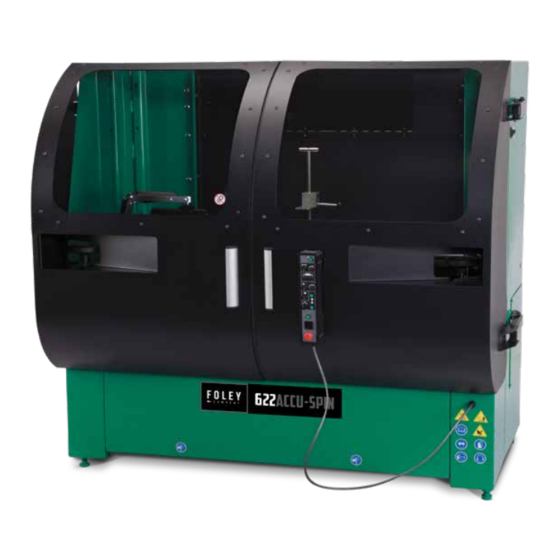
Page 16: Getting To Know Your Grinder
GETTING TO KNOW YOUR GRINDER - ORIGINAL INSTRUCTIONS - 1. FRONT CLAMP WITH HEIGHT ADJUSTER 4. REAR ROLLER SUPPORTS 2. SPIN DRIVE 5. ACCU-POSITIONING GAUGE (OPTIONAL) 3. CONTROL 1. FRONT CLAMP WITH HEIGHT ADJUSTER - Adjusts to accommodate various rollers and groomers and moves up and down to set the height of the cutting unit using a ratcheting system. - Page 17 GETTING TO KNOW YOUR GRINDER - ORIGINAL INSTRUCTIONS - CONTROLS 4. POWER SWITCH/FUSES 6. INFEED SELECT 2. START/RESET BUTTON 3. TRAVERSE DISPLAY CODES SPEED KNOB CODE DESCRIPTION 5. SPIN SPEED BLANK OFF/ E-STOP KNOB MACHINE ON - READY 6. INFEED AUTO PROGRAMS DOOR OPEN NOT ON TRAVEL...
-
Page 18: Operation
OPERATION - ORIGINAL INSTRUCTIONS - STEP 1: PLACING THE CUTTING UNIT PREPARE CUTTING UNIT FOR SHARPENING 1. Follow the cutting unit manufacturers' recommendations for proper maintenance when preparing the cutting unit for sharpening. 2. The reel to be sharpened should be thoroughly cleaned. 3. -
Page 19: Lifting Options
OPERATION-WINCH - ORIGINAL INSTRUCTIONS - LIFTING OPTIONS LIFTING A REEL INTO POSITION OPTIONAL BOOM WITH ELECTRIC WINCH 1. Position the reel on the floor so the front of the mower faces in the same direction as the front of the machine. 2. - Page 20 OPERATION - ORIGINAL INSTRUCTIONS - Read carefully before attempting to operate or service your optional electric winch or optional Lift or Workstation! Failure to comply with instructions could result in personal injury and/or property damage! FOR YOUR OWN SAFETY AND THAT OF OTHERS, THIS EQUIPMENT MUST BE USED AS RECOMMENDED BY THE MANUFACTURER.
-
Page 21: Troubleshooting
OPERATION - ORIGINAL INSTRUCTIONS - ELECTRIC WINCH (OPTIONAL) TROUBLESHOOTING This unit is activated via the switch at the end of the If the winch fails to operate, the circuit breaker on one foot cord. To remove wire rope from the winch, the end of the winch motor should be checked. -
Page 22: Lock Handle
OPERATION - ORIGINAL INSTRUCTIONS - ZERO THE REAR SUPPORT TABLE Before you align the GRINDING HEAD CARRIAGE to the reel of the cutting unit, true the REAR ROLLER SUPPORT PLATE to parallel to the V-BLOCKS SUPPORT to the Grind shaft. To move Unlock the LOCK HANDLES on the rear tooling plate and rotate the HANDWHEEL until the POINTER on the table alignes with the zero mark on the decal (see FIG 15). - Page 23 OPERATION - ORIGINAL INSTRUCTIONS - LOAD THE CUTTING UNIT T-HANDLE front TOOLING v-blocks rear roller clamp LOCK KNOB 1. Place the rear roller of the cutting unit into the V-BLOCKS (as shown above). It may be necessary to move the FRONT HEIGHT ADJUSTER into a position to receive the front roller. This is done by unlocking the LOCK HANDLE and sliding the FRONT HEIGHT ADJUSTER in or out in order for the front roller of the cutting unit to be placed on the FRONT HEIGHT ADJUSTER.
- Page 24 - ORIGINAL INSTRUCTIONS - STEP 2: SO MODEL - TOUCH OFF- WHEEL TO REEL ALIGNMENT OF GRINDING SHAFT TO REEL Release the Traverse Lock handle to move the grinding wheel left and right by hand. To align the grinding shaft to the reel, bring the shaft up so that the spin wheel is about ¼...
-
Page 25: Led Indicators
- ORIGINAL INSTRUCTIONS - STEP 2: SG MODEL - POSITION THE GRINDING WHEEL TO THE CUTTING UNIT Using the Positioning Guage will align the Wheel to the Reel and will remove taper when spin grinding without the need for a pi tape or taper checker. Make sure that the ACCU-POSITIONING GAUGE is on the rear pin position first. -
Page 26: Horizontal Positioning
OPERATION - ORIGINAL INSTRUCTIONS - 4. Press the RESET/CHECK BUTTON again to take the left side reading. The BLUE LED and RED LED will flash once. 5. Retract the GAUGE PIN and move the GRINDING CARRIAGE to the right until the decal on the ACCU- POSITIONING GAUGE aligns with the decal on the TOOLING BAR. - Page 27 OPERATION - ORIGINAL INSTRUCTIONS - 1. Move the ACCU-POSITIONING GAUGE to the FRONT PIN for HORIZONTAL POSITIONING. 2. Unlock the LOCK HANDLES on the REAR SUPPORT PLATE. 3. Release the TRAVERSE LOCK HANDLE (see FIG. 15) and move the GRINDING WHEEL to the left side of the cutting unit (see FIG.
- Page 28 OPERATION - ORIGINAL INSTRUCTIONS - STEP 3: SPIN GRINDING CONNECT SPIN DRIVE Choose which side of the reel you want to spin from and install the SPIN DRIVE MOTOR with the correct adapter. This will generally be the same drive system component used for backlapping see FIG.
- Page 29 OPERATION - ORIGINAL INSTRUCTIONS - SET TRAVEL LIMITS Set the TRAVEL LIMITS of the grinding wheel by either manually moving the wheel or by pressing the TRAVERSE SWITCH to ON and turning up the TRAVERSE SPEED KNOB. 1. Lower the grinding wheel by pressing the downfeed button 5-10 times.
-
Page 30: Auto Program
OPERATION - ORIGINAL INSTRUCTIONS - SPIN GRIND traverse switch spin drive motor SWITCH grinding wheel motor infeed/outfeed Traverse clamp 1. Before spin grinding, lock the TRAVERSE CLAMP and check that all LOCK HANDLES are tightened. 2. Close the doors. The grinding wheel motor and spin drive will not operate with the doors open. 3. - Page 31 OPERATION - ORIGINAL INSTRUCTIONS - PROGRAM INFEEDS TOTAL INFEED TOTAL PASSES .003" .006 .009" .012" .015" NOTE: SETUP PROCEDURE FOR SPIN DRIVE RPM SPIN DRIVE RPM DURING SPIN GRINDING IS VERY IMPORTANT IN ACHIEVING A QUALITY GRIND. THE DIAMETER OF THE REEL AND THE NUMBER OF BLADES ON THE CUTTING UNIT YOU ARE GRINDING WILL DETERMINE THE OPTIMAL SPIN SPEED.
- Page 32 - ORIGINAL INSTRUCTIONS -...
Need help?
Do you have a question about the 622 SO and is the answer not in the manual?
Questions and answers