Table of Contents
Advertisement
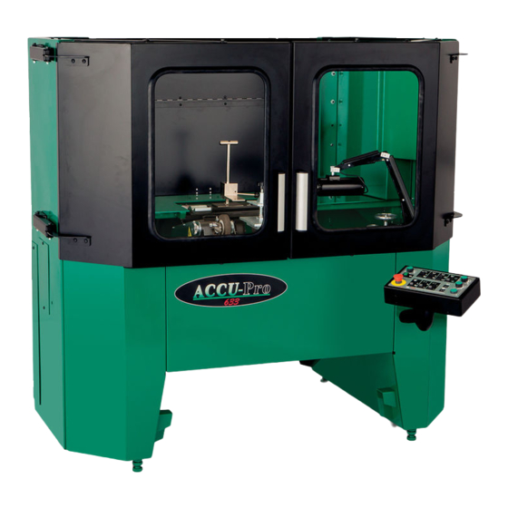
653 ACCU-Master
633 ACCU-Pro with
ACCU-Touch 3
AUTO-INDEX
SPIN/RELIEF
REEL GRINDER
THIS BOOK CONSISTS OF TWO MANUALS:
The OPERATOR'S MANUAL, which contains all the
information to install, operate, and perform daily
maintenance on this equipment.
The SERVICE MANUAL, which is used by the
maintenance department to do all maintenance
except routine daily maintenance.
Advertisement
Table of Contents

Related Manuals for Foley 653 ACCU-Master


Summary of Contents for Foley 653 ACCU-Master
- Page 1 653 ACCU-Master 633 ACCU-Pro with ACCU-Touch 3 AUTO-INDEX SPIN/RELIEF REEL GRINDER THIS BOOK CONSISTS OF TWO MANUALS: The OPERATOR'S MANUAL, which contains all the information to install, operate, and perform daily maintenance on this equipment. The SERVICE MANUAL, which is used by the maintenance department to do all maintenance except routine daily maintenance.
- Page 2 We are committed to: Providing superior customer support, training, and service. Manufacturing the highest quality products at an unequaled value. Setting the industry standard by investing in technological product innovation. Manufacturing products specifically designed to maintain original equipment manufacturers' specifications. Interacting with and supporting all original equipment manufacturers.
- Page 3 ORIGINAL INSTRUCTIONS 653/633 AUTO - INDEX SPIN / RELIEF REEL MOWER GRINDER Patent No. 5,321,912 6,010,394 & 6,290,581 6,685,544 & 6,699,103 Additional Patents Pending OPERATOR'S MANUAL YOU MUST THOROUGHLY READ AND UNDERSTAND ALL MANUALS BEFORE OPERATING THE EQUIPMENT, PAYING PARTICULAR ATTENTION TO THE WARNING AND SAFETY INSTRUCTIONS.
- Page 4 IMPORTANT SAFETY MESSAGE This manual covers the installation and operation of this reel grinder, there is an additional manual that addresses the service of this equipment. As manufacturers of reel grinders, we want to confirm to you, our concern for safety. We also want to remind you about the simple, basic, and common sense rules of safety when using a reel grinder.
- Page 5 TABLE OF CONTENTS Safety Message ..........................4 Safety Instructions ........................... 5-13 Installation Instructions ........................14-17 Getting to Know your Grinder ......................17-22 Operating Instructions ........................23-50 Keep this manual handy for quick reference. Require all operators to read this manual carefully and become acquainted with all adjustments and operating procedures before attempting to operate the equipment.
- Page 6 SAFETY INSTRUCTIONS FIG. 1 653 ACCU-MASTER SPECIFICATIONS OPERATING CONDITIONS: THIS MACHINE IS INTENDED FOR INDOOR USE ONLY. AMBIENT TEMPERATURE: +5°C/ 40°F to +40°C/ 100°F RELATIVE HUMIDITY: 50% RH, +40°C / 100°F. Higher RH may be allowed at lower temperatures. - no condensation must be present.
- Page 7 SAFETY INSTRUCTIONS LOW VOLTAGE RELAY The grinder is equipped with a high-low voltage monitor which is factory preset at 100-140 VAC. If the voltage inside the control panel falls outside of the range of 100-140 VAC under load, the relay will open and trip out the magnetic starter. If this occurs, your power supply line is inadequate to run this machine and must be corrected before proceeding further with the grinder.
- Page 8 SAFETY INSTRUCTIONS TO AVOID INJURY, READ AND UNDERSTAND THE SAFETY ITEMS LISTED BELOW. IF YOU DO NOT UNDERSTAND ANY PART OF THIS MANUAL AND NEED ASSISTANCE, CONTACT YOUR LOCAL DEALER OR THE MANUFACTURER. 1. KEEP GUARDS IN PLACE and in working order. 13.
- Page 9 SAFETY INSTRUCTIONS IMPROPER USE OF GRINDING WHEEL MAY CAUSE BREAKAGE AND SERIOUS INJURY. GRINDING IS A SAFE OPERATION IF THE FEW BASIC RULES LISTED BELOW ARE FOLLOWED. THESE RULES ARE BASED ON MATERIAL CONTAINED IN THE ANSI B7.1 SAFETY CODE FOR "USE, CARE AND PROTECTION OF ABRASIVE WHEELS".
- Page 10 SAFETY INSTRUCTIONS SAFETY DECALS - LOCATION. IF ANY DECALS ARE DAMAGED, REPLACE THEM IMMEDIATELY! See next page for explanation of symbols and decals.
- Page 11 SAFETY INSTRUCTIONS READ AND UNDERSTAND AND LOCATE ALL DECALS ON THIS MACHINE BEFORE OPERATING THIS EQUIPMENT. Use a Fork Lift with a minimum of Keep visitors at a safe distance away from the equipment. 48" [122cm] long forks to move this Equipment.
- Page 12 SAFETY INSTRUCTIONS SAFETY DECALS - LOCATION. IF ANY DECALS ARE DAMAGED, REPLACE THEM IMMEDIATELY! See next page for explanation of symbols and decals.
- Page 13 SAFETY INSTRUCTIONS READ AND UNDERSTAND AND LOCATE ALL DECALS ON THIS MACHINE BEFORE OPERATING THIS EQUIPMENT. Keep visitors at a safe distance away from Power cord may be a trip hazard. the equipment. Secure the power cord in a manner that removes it as a trip hazard.
- Page 14 INSTALLATION INSTRUCTIONS REMOVE GRINDER FROM WOOD PALLET To remove the grinder from the wood pallet, unbolt the brackets that hold the frame to the wood pallet. Use a fork lift to lift the machine from the pallet. See FIG. 7 on page 15. THE 633 UNIT WEIGHS 1450- 1600LBS.
- Page 15 INSTALLATION INSTRUCTIONS LIFTING LOCATION A forklift or pallet jack can be used to move or position this equipment. The forklift must have forks that are a minimum of 48" [122cm] long. When using a forklift lift in the center of the machine and be sure the forks extend all the way from the front to the back of the machine.
- Page 16 INSTALLATION INSTRUCTIONS POWER INSTALLATION IF THE MACHINE DOES NOT HAVE A PLUG ON THE END OF THE MAIN POWER CORD, A PLUG OR CONNECTOR THAT COMPLIES TO THE LOCAL LAWS AND REGULATIONS SHOULD BE INSTALLED BY A QUALIFIED ELECTRICIAN. THE PLUG IS CLASSIFIED AS A CATEGORY 0 MAIN DISCONNECT. DO NOT WIRE THIS MACHINE DIRECTLY TO A POWER SOURCE WITHOUT A PLUG OR CONNECTOR UNLESS A DEVICE THAT MEETS THIS CATEGORY 0 MAIN DISCONNECT REQUIREMENT IS USED TO PROVIDE POWER TO THE MACHINE.
- Page 17 INSTALLATION INSTRUCTIONS 120 VOLT MODEL ONLY. Plug the control box power cord into a standard 120VAC 20-amp grounded receptacle. See FIG. 10. 120 VAC 20 AMP STANDARD PLUG FOR NORTH AMERICA. When installing the grinder, the following guidelines should be used to establish the wire size between the power panel in your building and the grinder receptacle.
- Page 18 GETTING TO KNOW YOUR GRINDER SYSTEMS 1. ACCU-POSITIONING 3. FRONT CLAMP WITH GAUGE AND CYLINDER STOP HEIGHT ADJUSTER 2. ACCU-REEL SELECTOR 4. SPIN DRIVE 5. ACCU-TOUCH 3 CONTROL 1. ACCU-POSITIONING GAUGE AND CYLINDER STOP- Used in conjunction with the ACCU-Touch 3 Controller to position the cutting unit vertically and horizontally into the grinder.
- Page 19 GETTING TO KNOW YOUR GRINDER CONTROLS 2. RESET BUTTON ACCU-TOUCH 3 CONTROL ACCU-TOUCH 3 SCREEN 3. TRAVERSE SPEED KNOB FIG. 12 1. EMERGENCY STOP BUTTON 1. EMERGENCY STOP BUTTON or E-STOP Pressing will stop the flow of power to all motors. To restore power, pull up out on the red button and press the RESET SWITCH.
- Page 20 GETTING TO KNOW YOUR GRINDER TOUCH DISPLAY SCREEN EXPLANATIONS Review the following touch screen descriptions before proceeding with the instructions. EMERGENCY STOP SCREEN This screen is displayed when the EMERGENCY STOP BUTTON is pressed or the doors are opened while the machine is running.
- Page 21 GETTING TO KNOW YOUR GRINDER ALARMS SCREEN A message describing the problem will be displayed. If there is more than one problem they all will be displayed. LOW VOLTAGE DETECTED FIG. 16 CHECK BACK/PREVIOUS Press CHECK to acknowledge the alarm and clear it from the list. POPUP ALARM SCREEN Indicates a process error with a visual description of how to correct the error.
- Page 22 GETTING TO KNOW YOUR GRINDER TOUCHSCREEN NAVIGATION HOME Press to go to the START/REEL SETUP SCREEN. QUICK SPIN Press to go to the SPIN setup screen. QUICK RELIEF Press to go to the RELIEF setup screen. QUICK POSITIONING Press to go to to the POSITIONING setup screen. FORWARD Press to go one screen forward.
- Page 23 OPERATION The Four Basic Steps to grind the reel of a cutting unit include: 1. Place the Cutting Unit 2. Position the Grinding Head Carriage 3. Spin Grind 4. Relief Grind PREPARE THE CUTTING UNIT FOR SHARPENING Follow the cutting unit manufacturers recommendations for proper maintenance when preparing the cutting unit for sharpening.
- Page 24 OPERATION PRESS START BUTTON FIG. 21 UNIT SELECTION SCREEN 1. Select the REEL TYPE by manufacturer to be ground. 2. Select the DIAMETER of the reel to be ground. 3. Select the BLADE COUNT of the reel to be ground. These icons will not appear until the operator has selected the reel manufacturer, diameter, and...
- Page 25 OPERATION RELIEF ANGLE SELECT REEL MANUFACTURER AND DIAMETER INDICATOR FIG. 23 FIG. 24 RELIEF ANGLE ADJUSTER V-BLOCK LOCK PIN Place the ACCU-REEL POSITIONER to the correct position based on manufacturer and reel diameter. To move the ACCU-REEL POSITIONER pull up on the lock pin and move the assembly to the desired position. To lock the assembly in the correct position release the lock pin and move the assembly until the lock pin locks into position.
- Page 26 OPERATION There are 2 optional pieces of equipment that can be purchased to load a cutting unit. Before starting, read and understand all safety information in this manual and the manual that came with your equipment. Safety information for loading and operational instructions have been included on the following pages.
- Page 27 OPERATION READ CAREFULLY BEFORE ATTEMPTING TO OPERATE OR SERVICE YOUR OPTIONAL ELECTRIC WINCH OR OPTIONAL WORKSTATION! FAILURE TO COMPLY WITH INSTRUCTIONS COULD RESULT IN PERSONAL INJURY AND/OR PROPERTY DAMAGE! FOR YOUR OWN SAFETY AND THAT OF OTHERS, THIS EQUIPMENT MUST BE USED AS RECOMMENDED BY THE MANUFACTURER.
- Page 28 OPERATION The winch is designed to pull 400 lbs (180 KG) for 20 seconds on the wire rope layer closest to the drum. Attempts to pull more than this weight or exceed the duty cycle (on time) may cause damage to the winch or wire rope.
- Page 29 OPERATION PLACE THE CUTTING UNIT If loading from the rear of the machine it may be necessary to remove the REAR ROLLER CLAMP. To remove the REAR ROLLER CLAMP, turn the clamp 90 degrees so that the top T-HANDLE is pointing front to back and lift up on the clamp.
- Page 30 OPERATION SET THE HEIGHT GAUGE ROD REEL STOP LOCK HANDLE FIG. 33 ACCU-POSITIONING GAUGE STORAGE To set the height of the cutting unit use the ACCU- FIG. 34 POSITIONING GAUGE which is stored in the cabinet on the right handside of the inside of the machine. See FIG. 33. 1.
- Page 31 OPERATION REEL STOP LOCK HANDLE ALIGNMENT FIG. 35 INDICATOR LOWEST BLADE OF FIG. 36 CUTTING UNIT HEIGHT ADJUSTER DIRECTIONAL TOGGLE To set the height of the cutting unit: 1. Place the round REEL STOP on top of the GAUGE ROD on the ACCU-POSITIONING GAUGE. 2.
- Page 32 OPERATION STEP 2: POSITION THE GRINDING HEAD CARRIAGE Before you align the GRINDING HEAD CARRIAGE to the reel of the cutting unit, true the GRINDING HEAD CARRIAGE parallel to the ACCU-REEL POSITIONER V-BLOCKS SUPPORT by adjusting the CROSS SLIDE ASSEMBLY. Unlock the ORANGE LOCK HANDLE on the CROSS SLIDE ASSEMBLY and rotate the ORANGE HANDWHEEL until the DIAL INDICATOR on the CROSS SLIDE ASSEMBLY reads "0"...
- Page 33 OPERATION VERTICAL POSITIONING CROSS SLIDE GREY HANDWHEEL FIG. 41 GREY LOCK HANDLE To position the GRINDING HEAD CARRIAGE vertically, place the ACCU- POSITIONING GAUGE on the lower pin. Next, unlock the GREY LOCK HANDLE on the CROSS SLIDE ASSEMBLY. Then release the BELT CLAMP handle.
- Page 34 OPERATION 9. Press LOCKING TAB on the side of the ACCU- POSITION GAUGE to release the GAUGE ROD. You may have to rotate the reel slightly to allow the GAUGE ROD to travel between the reel blades. NOTE: It is important to NOT move or rotate the gauge.
- Page 35 OPERATION STEP 3: SPIN GRINDING PRESS SPIN GRIND TO CONTINUE. GRINDING HEAD POSITIONS SPIN/RELIEF The FINGER AND BODY ASSEMBLY of the GRINDING HEAD rotates on the GRINDING HEAD HOUSING to change positions between spin grinding and relief grinding. To change the position of the FINGER AND BODY ASSEMBLY, pull out the PLUNGER PIN on the left side of the GRINDING HEAD HOUSING.
- Page 36 OPERATION ORIGINAL INSTRUCTIONS CONNECT SPIN DRIVE The SPIN DRIVE attaches to the end of the reel shaft or a drive system component. Consult the CUTTING cutting unit manufacturer for proper spin drive UNIT placement and attachment. The SPIN DRIVE has a 1/2" male square end. To spin the reel you will need an adapter to connect the SPIN DRIVE to the cutting unit.
- Page 37 OPERATION SET TRAVEL LIMITS TRAVERSE STOP ICON Move the grinding wheel up to within an 1/8" [3 mm] of reel by pressing INFEED. Set the TRAVEL LIMITS of the grinding head by either manually moving the GRINDING HEAD CARRIAGE or pressing the TRAVERSE icons on the screen.
- Page 38 OPERATION TEST GRIND 5. Traverse to the HOME POSITION. NOTE: The Home position is when the grinding 1. Close the doors (the grinding wheel motor and head is on the right side travel limit and the right spin drive will not operate with the doors open). side travel limit sensor is illuminated.
- Page 39 OPERATION RUN A SPIN GRIND PROGRAM Select a program from the 5 preset programs or, if there are programs that were previously saved, press LOAD to access the PROGRAM LOAD SCREEN. You may edit the values by pressing on the value. A screen will appear that will allow you to type in a new value.
- Page 40 OPERATION SPIN SPEED AJDUSTMENT NOTE: SPIN DRIVE RPM in spin grinding is very important to achieving a quality grind. The Accu-Touch 3 Control initially establishes a spin speed based on the reel manufacture and cutting unit information that was input. Generally, the SPIN DRIVE RPM for spin grinding will be between 180 RPM and 380 RPM. However, for all reels, there is an optimum SPIN SPEED where there is an AGGRESSIVE, yet SMOOTH grind.
- Page 41 OPERATION CYCLES REMAINING INFEED BY .001" RUN/PAUSE PROGRAM OUTFEED BY .001" SPIN DRIVE CANCEL MOTOR SPEED LEVEL INDICATOR DECREASE SPIN SPEED INCREASE SPIN SPEED SPIN PROGRAM RUN SCREEN FIG. 61 If you wish to inspect the reel in the middle of a grind program, press PAUSE PROGRAM. The program will finish the traverse cycle it is currently on and then stop at the HOME position.
- Page 42 OPERATION STEP 4: RELIEF GRIND FIG. 63 PRESS THE RELIEF GRIND ICON TO CONTINUE. Pull the left side PLUNGER PIN and rotate the FINGER AND BODY ASSEMBLY up (counter clockwise looking from the right side) to the RELIEF position until the left side PLUNGER PIN locks into position. NOTE: The plunger pin must be fully engaged with the RELIEF ADJUSTER KNOB for proper function.
- Page 43 OPERATION SET RELIEF GRIND ANGLE RELIEF ANGLE SCALE Use ADJUSTER KNOB to set RELIEF ANGLE. FIG. 66 CORRESPONDING ANGLE FIG. 67 RELIEF ANGLE ADJUSTMENT To adjust the RELIEF ANGLE ADJUSTER, turn the ADJUSTER KNOB clockwise for more clearance or counter- clockwise for less clearance until you have reached the desired angle that corresponds with the number on the menu on the ACCU-REEL POSITIONER.
- Page 44 OPERATION INDEX STOP FINGER ADJUSTMENTS The FINGER AND BODY ASSEMBLY has two fingers. See FIG. 68 & 69. When relief grinding, the movable INDEX STOP FINGER moves from the RELIEF FINGER SIDE (back side) of the reel blade when traversing from right to left, to the grinding wheel side (front side) of the reel blade when traversing from left to right.
- Page 45 OPERATION SELECT SPIN DRIVE POSITION Verify the SPIN DRIVE MOTOR position and the number of blades on the reel. CHOOSE SPIN MOTOR LOCATION FIG. 71 SET TRAVEL LIMITS INFEED the GRINDING HEAD up until there is minimal clearance between the reel blade and the GRINDING WHEEL.
- Page 46 OPERATION SPIN DRIVE MOTOR SWITCH GRIND MOTOR SWITCH MANUAL TRAVERSE INFEED TRAVERSE TO OUTFEED TRAVEL LIMITS FIG. 75 TEST GRIND 1. Close all the doors, the GRINDING WHEEL MOTOR or SPIN DRIVE will not operate with the doors open. 2. Press the SPIN DRIVE. NOTE: The SPIN DRIVE will apply a torque load against the fingers. The RELIEF TORQUE POTENTIOMETER is preset based on cutting unit input.
- Page 47 OPERATION VERIFY BLADE COUNT INPUT AMOUNT SELECT A PRE-SET OF INFEED IN .001" PROGRAM INPUT NUMBER OF INFEEDS PRESS WHEN YOU LOAD A SAVED HAVE SET DESIRED PROGRAM PARAMETERS FIG. 76 RELIEF GRIND PROGRAM 1. Select a program from the 5 PRESET PROGRAMS or, if there are programs that were previously saved, press LOAD to access the Program Load Screen.
- Page 48 OPERATION TRAVERSE DRIVE RPM It is recommended to relief grind between around 15-20 feet per minute [4 meters per minute]. Grinding at a slower traverse speed, 10 feet per minute [3 meters per minute] as an example, will give a better finish but will extend the grind cycle time.
- Page 49 OPERATION LOADING A PROGRAM To load a program go to the LOAD PROGRAM Screen. You can access this screen by pressing LOAD from the Spin or Relief Program Screen. The LOAD PROGRAM screen will display the 15 custom programs available. The program will be blank until one is saved to that position.
- Page 50 GRINDING OTHER REELS PLACE A CUTTING UNIT NOT LISTED ON THE ACCU-REEL POSITIONER If the cutting unit is not listed on the menu on the left side of the ACCU-REEL POSITIONER you will need to use the POSITION LOCK on the right side of the ACCU-REEL POSITIONER. INSTALL CUTTING UNIT 1.
Need help?
Do you have a question about the 653 ACCU-Master and is the answer not in the manual?
Questions and answers