
Related Manuals for Foley 672


Summary of Contents for Foley 672
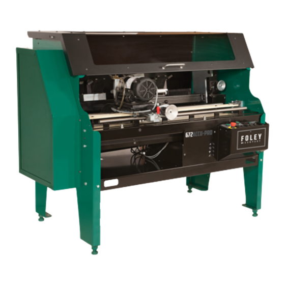
- Page 1 672 SEMI-AUTOMATIC BEDKNIFE GRINDER SERVICE MANUAL You must thoroughly read and understand this manual before assembling or maintaining the equipment, paying particular attention to the Warning & Safety instructions. 6727952 (07-20)
- Page 2 - ORIGINAL INSTRUCTIONS - IMPORTANT SAFETY MESSAGE As manufacturers of sharpening equipment, we want to confirm to you, our customers, our concern for safety. We also want to remind you about the simple, basic, and common sense rules of safety when using this equipment.
-
Page 3: Table Of Contents
- ORIGINAL INSTRUCTIONS - TABLE OF CONTENTS Safety Message ............................2 Safety Instructions ..........................3 -6 Service Data ............................7 Maintenance ............................8 - 13 Adjustments ............................14 - 17 Control Box Component ID ........................18 Troubleshooting ............................. 19 - 35 Parts Diagram ............................ -
Page 4: Safety Instructions
SAFETY INSTRUCTIONS - ORIGINAL INSTRUCTIONS - Safety Awareness Symbols are inserted into this manual to alert you to possible Safety Hazards. Whenever you see these symbols, follow their instructions. 1. KEEP GUARDS IN PLACE and in working order. 12. DON'T OVERREACH. Keep proper footing and balance at all times. - Page 5 SAFETY INSTRUCTIONS - ORIGINAL INSTRUCTIONS - IMPROPER USE OF GRINDING WHEEL MAY CAUSE BREAKAGE AND SERIOUS INJURY. Grinding is a safe operation if the few basic rules listed below are followed. These rules are based on material contained in the ANSI B7.1 Safety Code for "Use, Care and Protection of Abrasive Wheels".
- Page 6 SAFETY INSTRUCTIONS - ORIGINAL INSTRUCTIONS - UNPLUG THE EQUIPMENT PRIOR TO DOING ANY SERVICE ON THIS EQUIPMENT. FAILURE TO REMOVE POWER TO THIS EQUIPMENT BEFORE SERVICING MAY RESULT IN INJURY OR DEATH. IF POWER IS REQUIRED FOR TESTING OR TROUBLESHOOTING, THIS SHOULD BE PERFORMED BY A TRAINED PROFESSIONAL OR LICENSED ELECTRICIAN.
-
Page 7: Service Data
SERVICE DATA - ORIGINAL INSTRUCTIONS - SKILL AND TRAINING REQUIRED FOR SERVICING This Service Manual is designed for technicians who have the necessary mechanical and electrical knowledge and skills to reliably test and repair the Bedknife Grinder. For those without that background, service can be arranged through a local distributor. -
Page 8: Maintenance
MAINTENANCE LUBRICATION OF LINEAR BEARINGS STEP 1--Thoroughly clean the shafts. STEP 2--Flood spray the two shafts with a spray lubricant (do not use a teflon based lubricant) until the lubricant is dripping off the shafts. Then run the carriage back and forth through its full range of travel. - Page 9 MAINTENANCE - ORIGINAL INSTRUCTIONS - TESTING FOR PLAY IN THE BEARINGS USING DIAL INDICATOR MUST BE POSITIONED THE BEARING TESTER FORK OVER THE BEARING BEING TESTED AND LOCATED WITHIN 1" OF THE SIDE OF The traverse bearings on this grinder tend to wear THE CARRIAGE BASE.
- Page 10 MAINTENANCE CARRIAGE LINEAR BEARING REPLACEMENT LINEAR BEARING 1. Remove the optional carriage bellows (if used) from the carriage. 2. Remove the four screws of one linear bearing and slide the linear bearing off the end of the carriage shaft. 3. Insert a new linear bearing onto the end of the carriage shaft with the tension adjustment screw pointing outward.
- Page 11 See the warning above. 4. See FIG. 4 which illustrates which parts to return to Foley United. Make certain the bearing shipping guide is in place and then wrap the assembly in heavy paper and tape. Package the two magnet assemblies in a very sturdy shipping container with adequate filler material around and between the magnet assemblies.
- Page 12 MAINTENANCE - ORIGINAL INSTRUCTIONS - 7. Once the bearing is successfully on the profile rail, pump three pumps of grease from a standard grease gun into the bearing. Wipe off any excess grease that is visible. Then remove the grease fitting and install the plug supplied to you in the return package.
- Page 13 MAINTENANCE - ORIGINAL INSTRUCTIONS - CLEANING AND MAINTENANCE GUIDELINES FOR POLYCARBONATE WINDOWS Adherence to regular and proper cleaning procedures is recommended to preserve appearance and performance. DO NOT USE GASOLINE to clean polycarbonate windows! WASHING TO MINIMIZE SCRATCHING Wash polycarbonate windows with a mild dish-washing liquid detergent and lukewarm water, using a clean soft sponge or a soft cloth.
-
Page 14: Adjustments
ADJUSTMENTS - ORIGINAL INSTRUCTIONS - TO ADJUST THE PROXIMITY SWITCHES For the proximity switches to work properly and reverse the direction of the carriage at each end of a traverse, a distance of 3/16 in. +/- 1/32 [4.75 mm +/- 0.75] must be maintained between the 3/16IN.±1/32 top of the switch and the actuator bracket on the (4.75MM±0.75) - Page 15 ADJUSTMENTS - ORIGINAL INSTRUCTIONS - 3/4” TRAVERSE BELT TENSION To adjust the tension on the traverse belt tighten the screws and nuts located at the right side of the traverse belt. Tighten nuts until the compression springs measure 3/4". See FIG. 7. If the springs are not tensioned equally, uneven loading on the traverse system may cause parts to fail.
- Page 16 ADJUSTMENTS (Continued) - ORIGINAL INSTRUCTIONS - TO ELIMINATE INFEED HANDWHEEL BACKLASH If there is backlash in the Grinder Head Infeed handwheel (FIG. 20), there are two adjustment points on each to check: 1. Washers behind the handwheel: A. Remove the setscrew holding the calibration ring to the handwheel.
- Page 17 ADJUSTMENTS - ORIGINAL INSTRUCTIONS - TRAVERSE DRIVE CONTROL BOARD (TDC) Fwd Torque---FWD TQ The Traverse Drive Control Board has nine The Forward Torque setting determines the potentiometers and four switches as shown maximum current limit for driving the motor in on drawing 6734502 which is included.
- Page 18 ADJUSTMENTS - ORIGINAL INSTRUCTIONS - FIG. 10 FIG. 11...
-
Page 19: Control Box Component Id
- ORIGINAL INSTRUCTIONS - CONTROL BOX TRAVERSE DRIVE TRAVERSE BOARD LOW VOLTAGE CONTROL BOARD 3-AMP SLOW-BLO RELAY (LVR) (TDC) FUSE. BLUE TERMINAL GREY TERMINAL BLOCKS (TBW) BLOCKS (TBG) OR (TBB) TERMINAL STRIP #2 (TB2) MAGNETIC CONTACTOR (MAG) SECONDARY CIRCUIT BREAKER (SCB) MAIN CIRCUIT BREAKER (MCB) - Page 20 ELECTRICAL TROUBLESHOOTING SKILL AND TRAINING REQUIRED FOR ELECTRICAL SERVICING This Electrical Troubleshooting section is designed for technicians who have the necessary electrical knowledge and skills to reliably test and repair the electrical system. For those without that background, service can be arranged through your local distributor. This manual presumes that you are already familiar with the normal operation of the Grinder.
- Page 21 ELECTRICAL TROUBLESHOOTING (Continued) PROBLEM--AC Main Power Controls: no electrical power to control panel. Verify all wires shown on the wiring diagram on pages 54-55 are correct and pull on wire terminals with approximately 3 lbs force to verify there are no loose terminal connections and/or no loose crimps between wire and terminal.
- Page 22 ELECTRICAL TROUBLESHOOTING (Continued) Possible Causes Checkout Procedure No 120 Volts AC power to Secondary J. Check for 120V to SCB SCB (03SCB--) to nuetral (blue) Circuit Breaker (SCB) 6 Amp. terminal out of FTR for 120VAC Yes--Go to Step K. next. No--Check wires &...
- Page 23 ELECTRICAL TROUBLESHOOTING (Continued) PROBLEM--Machine Shuts off when you turn on Grind motor switch. Possible Cause Checkout Procedure Machine works A. Close the guard doors. Guard Door is open. Yes--end troubleshooting No--go to Step B. next Machine works B. Power delivered to the grinder is Low Voltage Relay is Yes--end troubleshooting inadequate.
- Page 24 ELECTRICAL TROUBLESHOOTING (Continued) PROBLEM-- Grinding motor not working. Assuming (SSS) System Start Switch is on with 120 volts AC to control panel and all other functions are working. Verify all wires shown on the wiring diagram on pages 54-55 are correct and pull on wire terminals with approximately 3lbs force to verify there are no loose terminal connections and/or no loose crimps between wire and terminal.
- Page 25 ELECTRICAL TROUBLESHOOTING (Continued) Possible Cause Checkout Procedure Bad Contacts in H. Verify power out of Grinding With relay pulled in (click) check (REL) Grinding motor Relay Motor Relay. GMS in ON position. Term T1 to Term T2 for 120 Volts (AC) Yes--Go to Step I.
- Page 26 ELECTRICAL TROUBLESHOOTING (Continued) PROBLEM--Traverse Drive not working. Assuming (SSS) System Start Switch is on with 120 volts AC to control panel and all other functions are working. Verify all wires shown on the wiring diagram on pages 54-55 are correct and pull on wire terminals with approximately 3lbs force to verify there are no loose terminal connections and/or no loose crimps between wire and terminal.
- Page 27 ELECTRICAL TROUBLESHOOTING (Continued) Possible Cause Checkout Procedure Check (TDC) terminals #A1 to #A2 for 90 No DC Voltage from (TDC) F. Check for 90 Volts DC across (TDC) Volts DC Traverse Drive Control terminals #A1 to #A2 this voltage Yes--go to Step G. next drives the DC traverse No--go to Step H.
- Page 28 ELECTRICAL TROUBLESHOOTING (Continued) PROBLEM--Traverse does not stop to reverse directions when flag goes under the proximity switch on the left side or right side of machine. Possible Cause Checkout Procedure If incorrect, adjust per adjustment Gap between flag A. Gap between flag and prox section of manual.
- Page 29 ELECTRICAL TROUBLESHOOTING (Continued) PROBLEM--Traverse speed control goes at one speed only. Possible Cause Checkout Procedure Traverse Drive Control Pin #8 to 7 Defective speed control A. Check potentiometer on control Pot full CCW Pot Full CW potentiometer panel. 0 VDC 9.75 VDC Pin #8 to 9 Pot full CCW...
- Page 30 ELECTRICAL TROUBLESHOOTING (Continued) PROBLEM--If the carriage traverses to one end of stroke or the other and it stops and does not reverse direction. Possible Cause Checkout Procedure The light coming on shows the proximity Proximity switch is not First check to see of proximity light comes on.
- Page 31 ELECTRICAL TROUBLESHOOTING (Continued) PROBLEM--Electromagents do not function. Assuming (SSS) System Start Switch is on with 120 volts AC to control panel and all other functions are working. Checkout Procedure Possible Cause Electromagnet switch (EMS) is Electromagnets work A. Turn (EMS) switch to on position. not on.
-
Page 32: Troubleshooting
TROUBLESHOOTING (Continued) PROBLEM--Tooling Bar Rotation Actuator does not Function Checkout Procedure Possible Cause Actuator works Actuator Motor Switch (AMS) is A. Push (AMS) switch to the up or Down Yes-- end troubleshooting not on. position. No-- go to Step B. next Actuator works Circuit Breaker tripped B. - Page 33 ELECTRICAL TROUBLESHOOTING (Continued) PROBLEM-- Coolant Pump not working. Assuming (SSS) System Start Switch is on with 120 volts AC to control panel and all other functions are working. Verify all wires shown on the wiring diagram on pages are correct and pull on wire terminals with 54-55 approximately 3lbs force to verify there are no loose terminal connections and/or no loose crimps between wire and terminal.
- Page 34 MECHANICAL Troubleshooting --PROBLEM-- --POSSIBLE CAUSE-- --REMEDY-- --REASON-- Top face of bedknife A--Grinding wheel is loading up Dress the wheel as prescribed in A loaded wheel creates undue is ground in a with grinding grit. the Operators Manual. pressure on the surface being convex shape (high ground.
- Page 35 MECHANICAL TROUBLESHOOTING (Continued) --PROBLEM-- --POSSIBLE CAUSE-- --REMEDY-- --REASON-- Grinding wheel is A--Wheel needs dressing. Dress the wheel before the finish- Wheel will glaze if not dressed glazing too quickly. grinding pass on each bedknife. See often enough. If grinding Operators Manual. wheel is not extended 1/2"...
- Page 36 PARTS LIST 6729503 MAIN BASE ASSEMBLY...
- Page 37 PARTS LIST (Continued) 6729503 MAIN BASE ASSEMBLY Diagram No. Part No. Description 1..........B190834 ........10-32 x 1/2 Button Head Socket Cap Screw 2..........B250816 ........1/4-20 x 1/2 Button Head Socket Cap Screw 3..........B251011 ........1/4-20 x 5/8 Socket Head Cap Screw 4..........
- Page 38 PARTS LIST 6729504 MAIN BASE ASSEMBLY DETAIL C DETAIL B DETAIL D DETAIL A...
- Page 39 86..........6709199 ........Prox Panel 87..........6729014 ........Actuator Assembly W168 (12V Rod End) 88..........6709209 ........Coolant Pump Assembly W118 89..........6709226 ........672 Decal W/CB Symbols 90..........6709568 ........Electrical Box Weldment 91..........6709569 ........Coolant Tank Weldment 92..........
- Page 40 PARTS LIST (Continued) 6729514 GRINDING HEAD ASSEMBLY...
- Page 41 PARTS LIST (Continued) 6729514 GRINDING HEAD ASSEMBLY Diagram No. Part No. Description 1..........B190611 ........10-24 x 3/8 Socket Head Cap Screw 2..........B192011 ........10-24 x 1-1/4 Socket Head Cap Screw 3..........B251216 ........1/4-20 x 3/4 Button Head Socket Cap Screw 4..........
- Page 42 PARTS LIST (Continued) 6729522 GRINDING HEAD HANDWHEEL ASSEMBLY...
- Page 43 PARTS LIST 6729522 GRINDING HEAD HANDWHEEL ASSEMBLY DIAGRAM NO. PART NO. DESCRIPTION 1..........B191213 ........10-24 x 3/4 Button Head Socket Cap Screw 2..........B255011 ........1/4-20 x 3-1/8 Socket Head Cap Screw 3..........C250420........1/4-20 x 1/4 Socket Set Screw Cap Point 4..........
- Page 44 PARTS LIST (Continued) 6729509 TRAVERSE & CARRIAGE ASSEMBLY...
- Page 45 PARTS LIST (Continued) 6729509 TRAVERSE & CARRIAGE ASSEMBLY DIAGRAM NO. PART NO. DESCRIPTION 1..........B190811 ........10-24X1/2 Shcs 2..........B191211 ........10-24X3/4 Shcs 3..........B250816 ........1/4-20X1/2 Bhscs 4..........B251026 ........1/4-28X5/8 Shcs 5..........B252016 ........1/4-20X1-1/4 Bhscs 6..........B252411 ........1/4-20X1-1/2 Shcs Full Thread 7..........
- Page 46 PARTS LIST (Continued) 6709562 BEDKNIFE SUPPORT ASSEMBLY 10/1/2015 2:35 PM 6709562.SLDDRW...
- Page 47 64............6709519 ..........Pivot Bearing Assembly 65............6729512 ..........Tooling Mounting Bracket Assembly 66............6729510 ..........Magnet Repair Assembly - INA 672 67............6729510 ..........Magnet Repair Assembly - INA 672 68............B251211 ..........Socket Head Cap Screw 1/4 -20 x 3/4 69............
- Page 48 PARTS LIST (Continued) 6729516 CONTROL PANEL ASSEMBLY...
- Page 49 24..........6709123 ........Switch Guard Base 25..........6709206 ........Control Panel Decal 26..........6709213 ........Control Travel Stop 27..........6709567 ........Control Panel Weldment 28..........6709572 ........Control Top Weldment 29..........6729519 ........Control Panel Sub Assembly 30..........6059050 ........672 Traverse Potentiometer...
- Page 50 6729519.SLDDRW 10/1/2015 3:10 PM 6759519 CONTROL PANEL SUB-ASSEMBLY PARTS LIST (Continued)
- Page 51 PARTS LIST (Continued) 6729519 CONTROL PANEL SUB-ASSEMBLY DIAGRAM NO. PART NO. DESCRIPTION 1..........D160666 ........Pan Head Self-Tapping Screw #8 x 3/8 Long 2..........D161266 ........Pan Head Self-Tapping Screw #8 x 3/4 Long 3..........R000480 ........#8 Lockwasher 4..........55223 ......... Terminal Strip Decal 5..........
-
Page 52: Wiring Diagram
WIRING DIAGRAM 6724519 102TB2-19 60TB2-19 103TB2-18 23TB2-18 104TB2-17 22TB2-17 105TB2-16 94TB2-16 106TB2-15 21TB2-15 13LVR-1 107TB2-14 96TB2-14 12LVR-8 93TB2-13 108TB2-13 09LVR-7 06LVR-6 13TB2-13 109TB2-12 25TB2-12 110TB2-12 111TB2-11 07TB2-11 95TBW-12 18TBW-12 92TBW-11 150TBW-11 112TB2-10 19TBW-10 15TBW-10 99TB2-10 113TB2-10 21TBG-9 149TBG-9 152TB2-9 159TB2-9 23TBG-8 68TBG-8a 151TB2-8... - Page 53 WIRING DIAGRAM 6724519 AMS-ACTUATOR MOTOR SWITCH ALM-ALARM - LOW BATTERY BAT-BATTERY (12VDC) CB1-CIRCUIT BREAKER 1 CB2-CIRCUIT BREAKER 2 CB3-CIRCUIT BREAKER 3 CB4-CIRCUIT BREAKER 4 CPS-COOLANT PUMP SWITCH EMS-ELECTROMAGNET SWITCH ESS-EMERGENCY STOP SWITCH FTR-LINE FILTER GMS-GRINDING MOTOR SWITCH LVR-LOW VOLTAGE RELAY MAG-MAGNETIC STARTER MCB-MAIN CIRCUIT BREAKER PWR-AC TO DC POWER SUPPLY...
- Page 54 ELECTRIC SCHEMATIC 6723519 115 VAC NEUTRAL MCB- AMS - ACTUAT 15 AMP BAT - BATTERY LINE FILTER CB1 - CIRCUIT CB2 - CIRCUIT SCB- 6 AMP CB3 - CIRCUIT CB4 - CIRCUIT CPS - COOLAN DSS - DOOR S ALARM CLOSES WHEN EMS - ELECTRO BATTER VOLTAGE IS BETWEEN 11-10VDC.
Need help?
Do you have a question about the 672 and is the answer not in the manual?
Questions and answers