ADTRAN MX2820 Quick Start Manual
Hide thumbs
Also See for MX2820:
- System manual (466 pages) ,
- Manual (2 pages) ,
- Quick start manual (2 pages)
Advertisement
CLEI: M3M1R00B_ _
Product P/N: 1186001L1
Front
Rear
D
ESCRIPTION
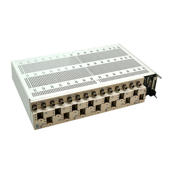
The MX2820 19-Inch Chassis (P/N 1186001L1) houses multiple M13
multiplexers that consolidate T1/E1 signals into T3 circuits. The
chassis houses seven redundant M13 multiplexers. The chassis also
houses a single System Controller Unit (SCU) that provides
management capabilities to the MX2820 system.
Features of the MX2820 system include the following:
•
1-to-1 redundancy
•
Hot-swappable MUX cards
•
Embedded SNMP and Telnet management
•
Simplified configuration through the VT100 terminal menu
structure
•
Meets the requirements for NEBS Level 3 compliance
T
-U
S
URN
P
TEPS
After unpacking the unit, inspect it for damage. If damage is noted,
file a claim with the carrier and then contact ADTRAN. Refer to
1. Attach mounting ears.
2. Attach cable tie bar, if necessary.
3. Mount chassis in rack.
!
WARNING
Care should be taken not to upset the stability of the equipment rack.
4. Remove appropriate fuses from fuse panel.
5. Remove metal cover from the right side of the back panel.
NOTE
Silk-screen on the metal cover references the following connections.
6. Wire wrap
CHN
posts and
route the wire downward.
7. If STS-1, wire wrap
CLKB
wire downward.
8. Wire wrap
ACO
posts and then route the wire downward.
9. Wire wrap
AUX1
,
AUX2
then route the wire downward.
10. Wire wrap
MAJ
and
CRIT
downward.
19-Inch Chassis
CLK
SCU
MUX
MUX
MUX
MUX
1186011
1186003
ACT
1186002
1186002
1186002
1186002
ALM
ACT
ACT
ACT
ACT
ALM
ALM
ALM
ALM
C
STAT
STAT
STAT
STAT
R
DS3
DS3
DS3
A
TEST
TEST
TEST
TEST
F
T
CLK A
STAT
STAT
STAT
STAT
DS1
DS1
DS1
TEST
TEST
TEST
TEST
CLK
1186011
ACO
1A
1B
2A
2B
CLKB
7
6
5
IN
OUT
IN
OUT
IN
OUT
DSX-3
DSX-3
DSX-3
7 IN
6 IN
5 IN
(T1/R1)
(T1/R1)
(T1/R1)
7 OUT
6 OUT
5 OUT
(T1/R1)
(T1/R1)
(T1/R1)
MIN
alarm relay posts and then
and
CLKA
posts and then route the
, and
AUX3
alarm input posts and
alarm posts and then route the wire
MX2820
MUX
MUX
MUX
MUX
MUX
1186002
1186002
1186002
1186002
1186002
ACT
ACT
ACT
ACT
ACT
ALM
ALM
ALM
ALM
ALM
STAT
STAT
STAT
STAT
STAT
DS3
DS3
DS3
DS3
DS3
DS3
TEST
TEST
TEST
TEST
TEST
STAT
STAT
STAT
STAT
STAT
DS1
DS1
DS1
DS1
DS1
DS1
TEST
TEST
TEST
TEST
TEST
3A
3B
4A
4B
5A
4
3
IN
OUT
IN
OUT
IN
DSX-3
DSX-3
4 IN
3 IN
(T1/R1)
(T1/R1)
4 OUT
3 OUT
(T1/R1)
(T1/R1)
11. Connect the frame ground on the barrier strip.
NOTE
Refer to the Safety and Regulatory Compliance Notice
(P/N 61186001L1-17) for this product when connecting the frame
ground.
RET B
12. Connect
strip.
NOTE
PWR = Respective –48 VDC or ±24 VDC source, RET = respective
return
13. Insert the appropriate fuses into the fuse panel.
14. Using a voltmeter, verify that the operating voltage is within
specifications for A and B power.
15. Remove appropriate fuses from panel and replace the metal
cover that was removed in step 5.
16. Insert appropriate fuses into panel, and if not done in step 2,
attach cable tie bar.
17. Connect 10/100Base-T Ethernet and NTWK MGMT X.25
interfaces.
18. Route DSX-3 coax and tie to upper tie bar.
19. Route DSX-1 IN cables below upper tie bar and tie to upper tie
bar.
20. Route DSX-1 OUT cables beneath lower tie bar and tie to lower
tie bar.
O
PERATIONAL
•
Electrical
o
Operating Voltage
I
–48 VDC Systems: –42 VDC to –56 VDC
I
–24 VDC Systems: –22 VDC to –27 VDC
I
+24 VDC Systems: +22 VDC to +27 VDC
•
Environmental
o
Operational Temperature Range: –40°C to +65°C
I
Without Fans: –40ºC to +50ºC
I
With Fans: –40°C to +65°C
o
Storage Temperature Range: –40°C to +85°C
o
Relative Humidity: up to 95%, noncondensing
jobAid
Issue Date: January 2012
Document P/N: 61186001L1-22D
MUX
MUX
MUX
MUX
MUX
1186002
1186002
1186002
1186002
1186002
ACT
ACT
ACT
ACT
ACT
ALM
ALM
ALM
ALM
ALM
STAT
STAT
STAT
STAT
STAT
DS3
DS3
DS3
DS3
DS3
TEST
TEST
TEST
TEST
TEST
STAT
STAT
STAT
STAT
STAT
DS1
DS1
DS1
DS1
DS1
TEST
TEST
TEST
TEST
TEST
5B
6A
6B
7A
7B
P4
R8
R6
A
U
X
2
1
R7
R5
1
P6
OUT
IN
OUT
N
A
J1
C
U
DSX-3
DSX-3
X
2
C
M
A
I
N
U
N
O
X
3
N
C
C
T
A
N
C
C
R
O
O
N
S
2 IN
1 IN
TB1
O
+
T
P
(T1/R1)
(T1/R1)
W
–
R
R
A
S
R
N
H
E
CLKB
C
T
R4
A
D3
P
D2
W
R
B
R
R10
E
T
B
R1
D1
2 OUT
1 OUT
R9
R2
(T1/R1)
(T1/R1)
J2
USE COPPER
-48V
, 3.75A
CONDUCTORS ONLY
PWR B
RET A
PWR A
,
,
, and
S
PECIFICATIONS
on the barrier
Advertisement
Table of Contents

Related Manuals for ADTRAN MX2820


Summary of Contents for ADTRAN MX2820
- Page 1 16. Insert appropriate fuses into panel, and if not done in step 2, After unpacking the unit, inspect it for damage. If damage is noted, attach cable tie bar. file a claim with the carrier and then contact ADTRAN. Refer to Warranty. 17. Connect 10/100Base-T Ethernet and NTWK MGMT X.25 1.
- Page 2 Bold indicates blue binder group. Pairs 1–25 do not use a binder. Warranty: ADTRAN will replace or repair this product within the warranty period if it does not ADTRAN CUSTOMER CARE: meet its published specifications or fails while in service. Warranty information can From within the U.S.
Need help?
Do you have a question about the MX2820 and is the answer not in the manual?
Questions and answers