ADTRAN MX2820 Quick Start Manual
Hide thumbs
Also See for MX2820:
- System manual (466 pages) ,
- Manual (2 pages) ,
- Quick start manual (2 pages)
Advertisement
Quick Links
MX2820
23 INCH
CHASSIS
CLEI: M3M1W00B_ _
DESCRIPTION
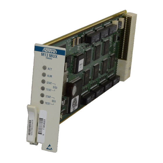
The MX2820 chassis houses multiple M13 multiplexers that consolidate T1/E1 signals
into T3 circuits. The MX2820 (P/N 1186001L2) houses nine redundant M13 multiplexers.
The MX2820 chassis also houses a single SCU that provides management capabilities to
the MX2820 system.
Features of the MX2820 include:
I
1:1 redundancy
I
Hot-swappable MUX cards
I
Embedded SNMP and Telnet management
I
Simplified configuration through the VT100 terminal menu structure
I
Meets the requirements for NEBS Level 3 compliance
TURN-UP STEPS
1.
Attach mounting ears.
2.
If necessary at this point, attach cable tie bar.
3.
Mount chassis in rack.
Warning: Care should be taken not to upset the stability of the equipment rack.
4.
Remove appropriate fuses from fuse panel.
5.
Remove metal cover from the right side of the back panel.
Note: Silkscreen on cover references the following connections:
6.
Wire wrap CHAIN posts and MIN alarm relay posts and route wire downward.
7.
If STS-1, wire wrap CLKB and CLKA posts and route wire downward.
8.
Wire wrap ACO posts and route wire downward.
9.
Wire wrap AUX3, AUX2, and AUX1 alarm input posts and route wire downward.
10. Wire wrap MAJ and CRIT alarm posts and route wire downward.
11. Connect frame ground on barrier strip.
Caution: Per GR-1089-CORE October 2002, Section 9, MX2820 system is designed and
intended only for installation in a DC-C (common) bonding and grounding
system. The chassis ground wire must be of equal or greater ampacity than the
wire connected to the VDC return.
The MX2820 system is not intended or designed for installation in a DC-I
(isolated) bonding and grounding system.
Note: A readily accessible disconnect device, such as a rackmount fuse and alarm panel
C A U T I O N
C A U T I O N !
that is suitably approved and rated should be incorporated in the fixed wiring.
SUBJECT TO ELECTROSTATIC DAMAGE
OR DECREASE IN RELIABILITY.
HANDLING PRECAUTIONS REQUIRED.
MX2820 23 INCH CHASSIS
Note: Connect to a reliably grounded VDC source, which is electrically isolated
from the AC source.
12. Connect RET B, PWR B, RET A, and PWR A on barrier strip.
Note: PWR = Respective –48 VDC or ±24 VDC source, RET = respective return
13. Insert appropriate fuses into fuse panel.
14. Using a voltmeter, verify that the operating voltage is within specifications
for A & B power.
15. Remove appropriate fuses from panel and replace the metal cover that was
removed in step 5.
16. Insert appropriate fuses into panel, and if not done in step 2, attach cable
tie bar.
17. Connect 10/100BaseT Ethernet and NTWK MGMT X.25 interfaces.
18. Route DSX-3 coax and tie to upper tie bar.
19. Route DSX-1 IN cables below upper tie bar and tie to upper tie bar.
20. Route DSX-1 OUT cables beneath lower tie bar and tie to lower tie bar.
OPERATIONAL SPECIFICATIONS
I
Operates from A or B input voltage power feeds:
–48 VDC Systems: –42 VDC to –56 VDC
–24 VDC Systems: –22 VDC to –27 VDC
+24 VDC Systems: +22 VDC to +27 VDC
I
Operates over extended temperature range of –40ºC to +50ºC without fans, and
–40ºC to +65ºC with fans.
I
Storage –40ºC to +85ºC. Relative humidity to 95 percent, noncondensing.
COMPLIANCE
I
The MX2820 chassis complies with UL 60950, NEBS Level 3, and
GR-1089-CORE.
I
The MX2820 chassis is intended for installation in Restricted Access Areas only.
I
This device complies with Part 15 of the FCC rules. Operation is subject to the
following two conditions: (1) This device may not cause harmful interference,
and (2) this device must accept any interference received, including interfer-
ence that may cause undesired operation.
I
The DSX-1, DS3, and 10/100BaseT Ethernet circuits are not to be connected to
outside plant facilities.
Code
I
Changes or modifications not
Power Code (PC)
expressly approved by ADTRAN
could void the user's authority
Telecommunication Code (TC)
to operate this equipment.
Installation Code (IC)
JOB
A
ID
61186001L2-22E
0403
Input Output
F
C
–
–
A
–
Advertisement

Related Manuals for ADTRAN MX2820


Summary of Contents for ADTRAN MX2820
- Page 1 T3 circuits. The MX2820 (P/N 1186001L2) houses nine redundant M13 multiplexers. Note: PWR = Respective –48 VDC or ±24 VDC source, RET = respective return The MX2820 chassis also houses a single SCU that provides management capabilities to 13. Insert appropriate fuses into fuse panel.
- Page 2 BRN/VOL WARRANTY BLK/BLU BLU/BLK VOL/SLT SLT/VOL ADTRAN will replace or repair this product within the warranty period if it does not meet its BLK/ORG ORG/BLK WHT/BLU BLU/WHT published specifications or fails while in service. Warranty information can be found at...
Need help?
Do you have a question about the MX2820 and is the answer not in the manual?
Questions and answers